A primary reason for the pervasive character of such research is that free-standing (FS), coefficient of
thermal expansion (CTE)--matched, and lattice-matched GaN substrates of suitable quality and size are unavailable.
Without homoepitaxial or native substrates, misfit dislocations will form due to
lattice mismatch at the
epitaxy-substrate interface, and
cracking and bowing will occur due to the CTE mismatch, thereby limiting the quality of the epi and device
layers.
Typically, to make higher quality devices, very difficult and complicated overgrowth techniques such as ELOG (epitaxial
lateral overgrowth) or LEO (lateral epitaxial overgrowth) or Pendeo-
epitaxy are employed, but the resulting material is non-uniform in morphology and crystalline quality.
Further, the resulting material typically has a high carrier concentration due to
impurity incorporation from the masking material.
The lack of a suitable quality lattice-matched (Al,In,Ga)N substrate has impeded (Al,In,Ga)N device developers from realizing the full potential of the (Al,In,Ga)N device capabilities and slowed the development of this
material system.
The complexity and difficulties attendant the
lateral overgrowth techniques have prevented such approach from being satisfactorily commercially used.
High pressure crystal growth has been successful in producing small platelets (<20 mm
diameter and <1-2 mm thick) of less than 300 square millimeters area of
single crystal GaN but the GaN crystals have several problems.
This technique produces small platelets and the
scalability is difficult and the cost of the process is quite large compared to other alternatives.
These high levels of impurities limit the frequency range of devices produced on the substrates due to parasitic capacitances between device
layers and charge in the substrate and may inhibit
epitaxy nucleation on the substrate at sufficiently high
impurity concentrations.
Currently, the
boule diameter is limited to 13 millimeters, severely limiting the production of lost cost, high volume devices.
Another issue with these substrates is the extremely
high oxygen level, on the order of parts per million (ppm), which will likely reduce the
thermal conductivity of the substrates, making them less advantageous for
high frequency, high power devices.
In addition to affecting the
thermal conductivity, the high impurity incorporation in these substrates inhibits the production of controlled electrical
conductivity type substrates, namely p-type substrates.
These substrates are difficult to dope heavily by conventional techniques, making them less advantageous for vertical opto-electronic device structures.
In the case of AlN substrates, the substrate and associated devices are disadvantaged by high
ionization or
activation energy of acceptors and donors in the crystal, as compared to GaN substrates.
LAO and LGO are closely lattice-matched substrates (compared to SiC and
sapphire) and are available in reasonable quality and size, however, several issues exist that prevent their applicability to the GaN
material system.
Most importantly, LAO and LGO materials suffer from low
decomposition temperatures preventing them from being easily used for GaN growth at typical growth temperatures.
Li and Ga
desorption and
diffusion from the substrate into the epitaxial film and growth environment make
nucleation and high quality, impurity-free growth very difficult, thus limiting the applicability of this substrate.
Non-uniform polarity of the
substrate surface is also an issue, typically causing mixed polarity domains in the GaN epitaxial film.
The fabrication of vertical devices structures on such substrates also involves issues of
doping and suppression of
decomposition.
Because there have been no large area, freestanding GaN wafers commercially and readily available, there has been limited opportunity to develop the conditions to produce high quality epitaxial layer growth on FS GaN.
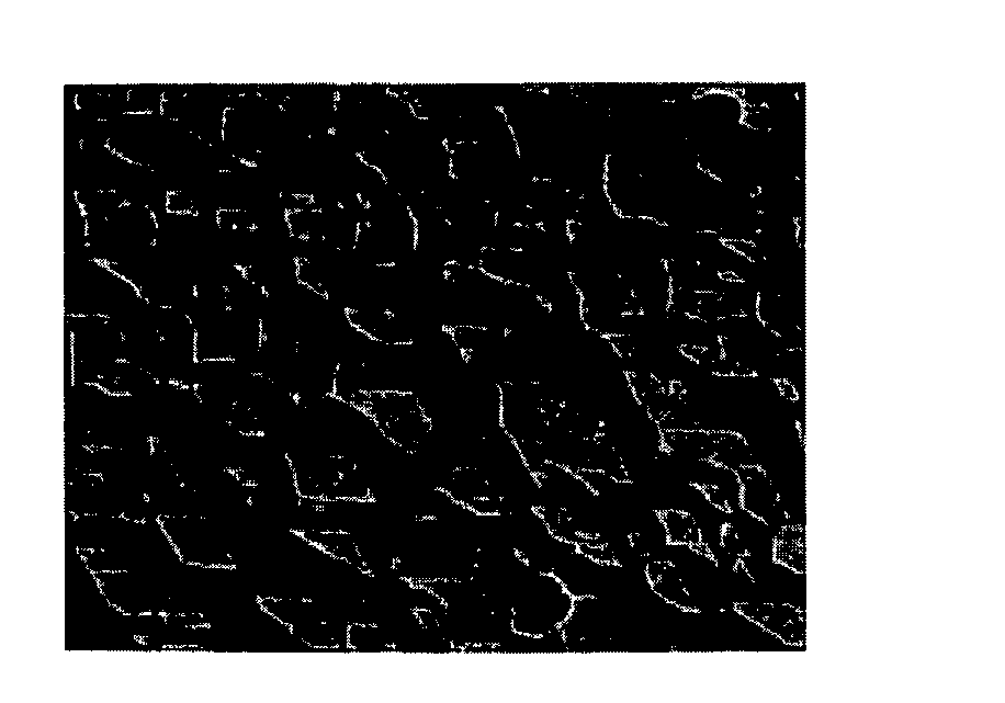
A significant issue relating to growth on FS GaN "as grown" or unfinished surfaces is that appreciable MOVPE thickness has to be deposited to smooth out
hillock morphology from the HVPE GaN.
Growing thicker
layers of epitaxy on the FS GaN substrate smooths out the "as grown" or unfinished FS GaN morphology, but at the expense of increased cost and longer
growth time for a device structure, which in turn increases the cost of the device structure growth and reduces the
throughput and profitability of the
vapor phase epitaxy (VPE) reactor operation.
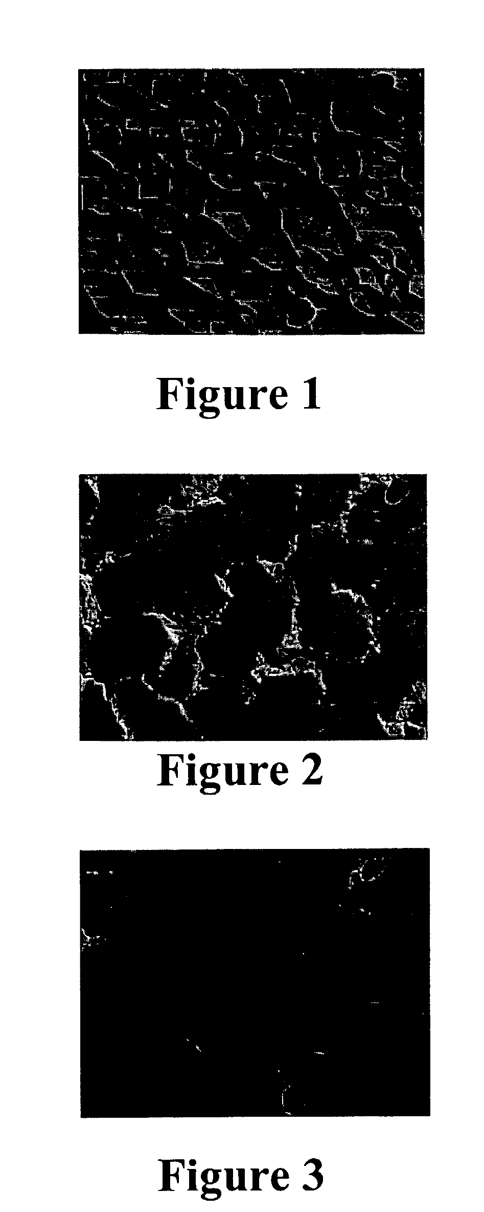
Another issue related to homoepitaxial growth on FS GaN substrates is that the backside of the GaN
wafer (N-face) tends to decompose during growth.
This decomposition tends to interrupt the epi growth surface.
Decomposition products escaping from the backside of the
wafer are transported to the growth area disturbing the growth conditions and causing interrupted morphology.
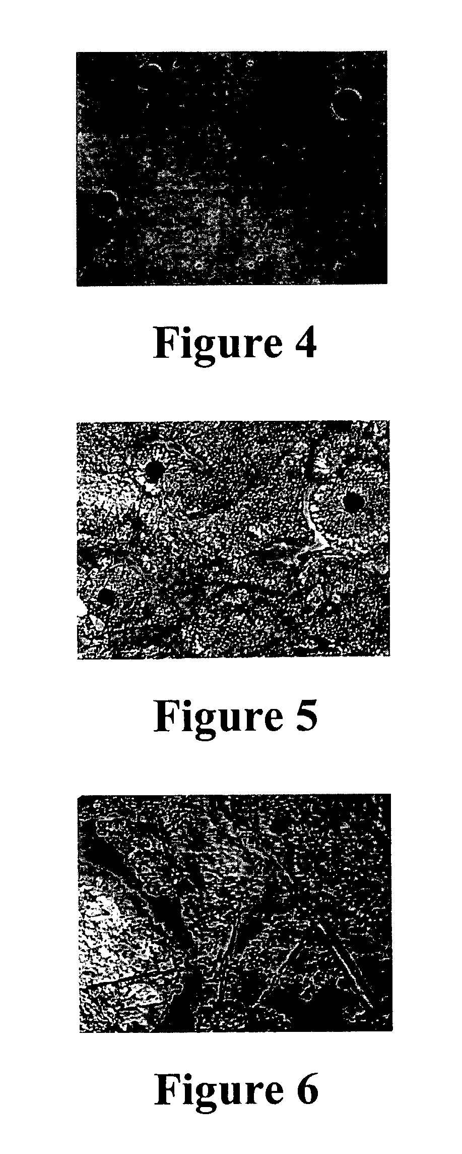
The substrate preparation, interface preparation upon heat-up and substrate cleaning, also create issues in MOVPE GaN growth on FS GaN substrates.
General reactor conditions may also affect epitaxial morphology for growth on FS GaN, resulting in poor interrupted morphologies.
Potential impurity and structural damage at the interface leading to charge accumulation at the substrate-epi interface is a potential issue for the use of FS (Al, Ga, In)N in
high frequency electronic devices.

