Superhydrophobic surface and method for forming same

a superhydrophobic surface and coating technology, applied in the superimposed coating process, liquid/solution decomposition chemical coating, manufacturing tools, etc., can solve the problems of insulator contamination becoming a major impediment to the interruption of electrical power supply, increasing leakage current, and ultimately flashing, etc., to improve the superhydrophobic effect, improve the contact angle, and reduce the effect of hysteresis

Inactive Publication Date: 2009-01-08
GEORGIA TECH RES CORP
View PDF51 Cites 188 Cited by
  • Summary
  • Abstract
  • Description
  • Claims
  • Application Information

AI Technical Summary

Benefits of technology

[0072]In another preferred embodiment, the present invention improves the superhydrophobic effect (higher contact angle and lower hysteresis) through the post-treatment of a surface that displays a contact angle greater than 150°, with a coupling agent. The effectiveness of the coupling agent is enhanced if the agent contains chemical elements that are known to be hydrophobic in nature. Silanes such as trichloro or tri(m)ethoxyl silanes are preferred. The present treatment overcomes the drawbacks of conventional techniques, in that it may be accomplished at or near ambient temperatures and pressures. The ambient nature of the present treatment means that many geometries or sizes of device/insulator can be treated, thereby removi

Problems solved by technology

In regard to high voltage applications, superhydrophobic properties would help limit or even prevent the accumulation of contaminants on the surface of the insulators, which can produce a conductive layer when wet, which can then lead to an increase in leakage currents, dry band arcing, and ultimately flashover.
In many parts of the world, insulator contamination has become a major impediment to the interrupted supply of electrical power.
Contamination on the surface of insulators gives rise to leakage current, and if high enough, flashover.
(1) Cleaning with water, dry abrasive cleaner, or dry ice can effectively remove loose contamination from insulator, but it is expensive, labor intensive and only a short term solution;
(2) Mobile protective coatings, including surface treatment with oils, greases and pastes, can prevent flashover, but have damaging results to the insulator during dry band arcing;
(3) Grease-like silicone coating components, usually compounded with alumina tri-hydrate (ATH), provide a non-wettable surface maintaining high surface resistance, and have been used as protective coatings for the past 30 years. A major strength of silicone grease lies in its ability to maintain a mobile water repellent surface, thereby controlling leakage current;
(4) Fluorourethane coatings were developed for high voltage insulators, but the field test was not successful, and its low adhesion to the insulators has been a problem; and
(5) Since 1970s, room temperature vulcanizing (RTV) silicone coatings have gained considerable popularity, and become the major products available in the market, such as Dow Corning's SYLGARD High Voltage Insulator Coatings (HVIC), CSL's Si-Coat HVIC, and Midsun's 570 HVIC. Service experience has indicated that of the various types of insulator coatings, the time between maintenance and RTV coating reapplication is the longest.
Yet, these conventional techniques do not prevent contamination, such as dust, accumulation on coating surfaces; thus, these serve only to manage the problem, and do not provide satisfactory performance in heavy contamination environments.
In long-term use, an insulator is subject to superficial soiling depending on the location at which it is used, which can considerably impair the original insulating characteristics of the originally clean insulator.
One problem aff

Method used


Image

  • Superhydrophobic surface and method for forming same
  • Superhydrophobic surface and method for forming same
  • Superhydrophobic surface and method for forming same

Examples


example i

Method Example I

[0217]TMOS (Precursor), IBTMOS (Coprecursor), and ethanol are first mixed together using the amounts given in TABLE 6 under “Material Example I.” HCl (0.1 M) is added to adjust the pH of the mixture to around 1.8-2.0. The reaction is started by heating to 60° C., and then holding for five (5) hours. After the reaction NH3H2O, 1.1M, a base, was added to the solution to initiate gelation of the polymer.

[0218]Before complete gelation, the solution may be cast onto a suitable substrate (microscope glass slide, elastomer, etc) to form a thin layer. The surface was covered to ensure slow evaporation of the ethanol and ammonia. After two (2) days, the film was completely gelled and the ethanol was completely evaporated. A thin silica layer was left on the substrate surface. Implementation on a glass microscope slide showed that the surface was superhydrophobic directly after coating due to the hydrophobic side chains present in IBTMOS coprecursor (FIGS. 18-19). TABLES 7-8 d...

example ii

Method Example II

[0222]TEOS (Precursor), TFPS (Coprecursor), and ethanol are first mixed together using the amounts given in TABLE 6 under “Material Example II.” HCl (1 M) is added to adjust the pH to around 1.8-2.0. The reaction was started by heating to 60° C., where the temperature was maintained for five (5) hours. After the reaction, 0.1 g ammonia hydroxide (29% wt) was added (1.1 M) to 2 g solution for gelation of the polymer.

[0223]Before complete gelation, the solution was cast onto a suitable substrate to form a thin layer. The surface was covered to ensure slow evaporation of the ethanol and ammonia. After two (2) days, the film was gelled and the ethanol was evaporated. A thin silica layer was left on the substrate, of which a suitable illustrative example is a glass microscope slide.

[0224]The surface is superhydrophobic due to the hydrophobic side chains present in TFPS coprecursor (FIGS. 20-21). FIG. 21 includes SEM micrographs of the TFPS-TEOS surfaces for different rea...

example iii

Method Example III

[0227]Initially, a eutectic liquid was formed by mixing choline chloride and urea together in a ratio of 2:1

[0228]A formulation is described in TABLE 6 under “Material Example III.” Tetraethoxysilane (TEOS—Precursor): 0.6 g, eutectic mixture (C—U): 1-6 g, ethanol: 1.5-3 g, 1M HCl aqueous solution: 0.3 g are all mixed together. Hydrolysis and condensation occurs after the addition of HCl to the mixture, and stirring for three (3) hours. The solution was coated onto a s suitable substrate. In this example the solution was then spin coated onto one (1) square inch glass microscope slides at 3000-6000 rpm to form uniform films. The coated glass slide was placed in a desiccator with a container of 1 ml ammonia (29%) at the bottom, to promote gelation. After two (2) days, the glass slide was removed from the desiccator and extracted with absolute ethanol for three (3) hours to remove the eutectic liquid in the film, and thus yield a porous thin film. The transmittance of...


PUM

PropertyMeasurementUnit
Temperatureaaaaaaaaaa
Timeaaaaaaaaaa

Abstract

The present invention is a method of applying Lotus Effect materials as a (superhydrophobicity) protective coating for various system applications, as well as the method of fabricating/preparing Lotus Effect coatings.

Description

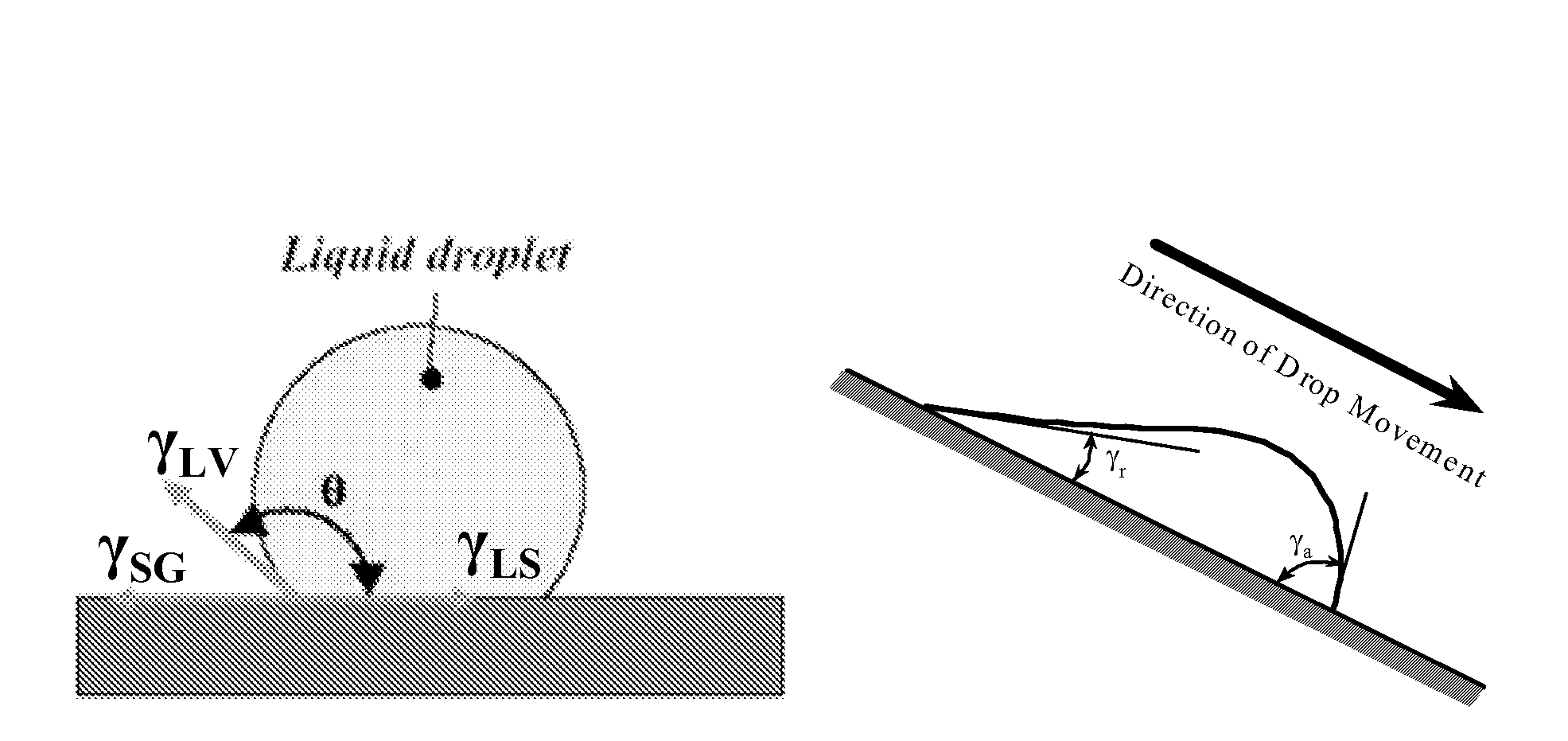
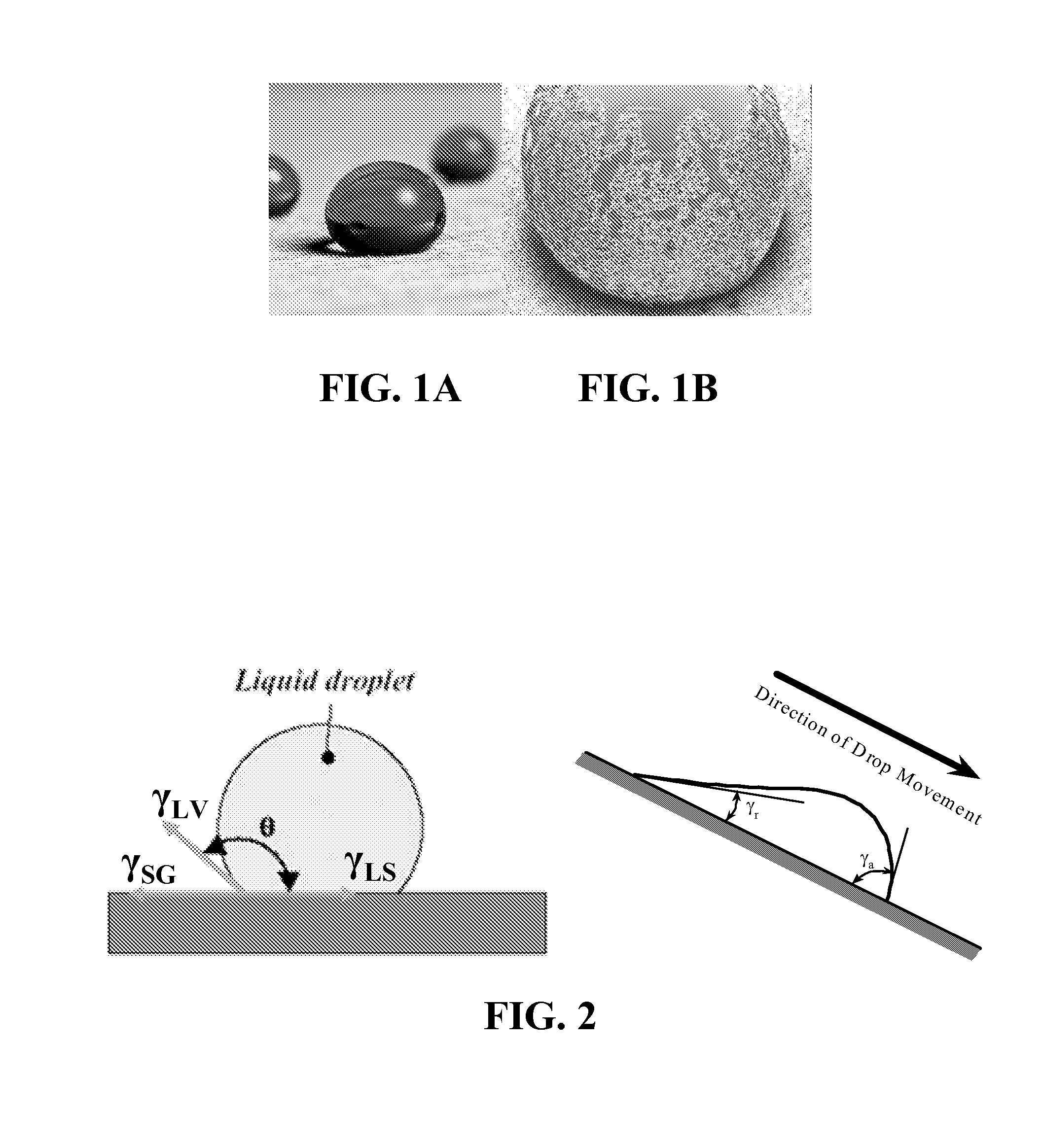
CROSS-REFERENCE TO RELATED APPLICATIONS[0001]Under the provisions of 35 U.S.C. § 119(e), this application claims the benefit of U.S. Provisional Application Nos. 60 / 786,305 filed 27 Mar. 2006, and 60 / 793,801 filed 23 Apr. 2006, both of which are incorporated herein by reference.BACKGROUND OF THE INVENTION[0002]1. Field of the Invention[0003]This invention relates generally to the field of superhydrophobic surface coatings, and methods for forming same.[0004]2. Description of Related Art[0005]The Lotus Effect is named after the lotus plant, and was first used for technical applications by Professor Wilhelm Barthlott from the University of Bonn. The Lotus Effect generally refers to two characteristic properties: superhydrophobicity and self-cleaning, although in some instances, either one of these properties provide the benefits of the Lotus Effect.[0006]Superhydrophobicity is manifested by a water contact angle larger than 150°, while self-cleaning indicates that loose (non-adhered) ...

Claims


Application Information

Patent Timeline
IPC IPC(8): B05D3/12B05D3/00B05D3/02B05D1/02B05D1/18B32B1/00B32B33/00
CPCC23C18/00Y10T428/25C23C24/00Y10T428/31504
Inventor XIU, YONGHAOZHU, LINGBOHESS, DENNIS W.WONG, CHING PINGXIAO, FEIHAMPTON, ROBERT N.LAMBERT, FRANKLIN C.
Owner GEORGIA TECH RES CORP
Why Eureka
Try Eureka