Process and device for smelting ferronickel and nickel-containing molten iron by using lower-nickel materials

A technology of molten nickel iron and materials, applied in the field of equipment to realize this process, can solve the problems of high sulfur content, high process cost, high energy consumption, etc.

Inactive Publication Date: 2009-09-23
丁家伟
View PDF9 Cites 27 Cited by
  • Summary
  • Abstract
  • Description
  • Claims
  • Application Information

AI Technical Summary

Problems solved by technology

However, as far as the current situation of nickel ore resources is concerned, the nickel-containing materials in my country are mainly concentrated in the sulfide paragenetic ore in Jinchuan, and its output is far from meeting the needs of the rapid development of the domestic economy.
There is a huge gap between my country's nickel production and nickel consumption. For this reason, my country has to consume a huge amount of foreign exchange every year to import a large number of nickel-iron alloys or import laterite nickel ore and serpentine from the Philippines, Brazil, Colombia, Australia, Canada and other countries. The imported laterite nickel ore and serpentine nickel ore are nickel-containing minerals mainly composed of nickel oxide. It is nickel-bearing peridotite after large-scale long-term weathering in tropical or subtropical regions. It is formed by leaching and metamorphism. It is a loose clay-like ore composed of iron, aluminum, silicon and other hydrous oxides. Due to the oxidation of iron, the rock is red, so it is called lateritic nickel ore. The content of nickel depends on the mining. The Ni content of the limonite layer is about 0.8-1.5%, the Ni content of the transition layer is about 1.5-1.8%, and the Ni content of the humus layer is about 1.8-3.0%. The process of extracting nickel is costly, complicated, low yield, and serious pollution, so the deposit has not been developed and utilized on a large scale for a long time
For this low-grade nickel material, there are currently two main processes for producing ferronickel in my country: one is to smelt ferronickel in a blast furnace. This process is characterized by a large output, but it costs a lot of money (about 30 million yuan for a 128 cubic meter blast furnace) , the production cost is high (the coke ratio is high, about twice that of the reduction method), and the blast furnace is severely damaged. For example, my country's patent application numbers 200510102985. Mix the ingredients for sintering to obtain sintered agglomerates, and then mix the sintered agglomerates with coke, lime / quicklime, dolomite and fluorite and then smelt them in a blast furnace to obtain ferronickel
This process is a method proposed in some areas of the country to use laterite nickel ore as a raw material and use blast furnaces (most of which are small blast furnaces that have been required to be eliminated by the state) to smelt and manufacture nickel-containing molten iron under the condition of high nickel prices. The production practice shows that , this method has obvious shortcomings: (1) the amount of slag is large (greater than 1120Kg / t); (2) the basicity of slag is low, which is not conducive to desulfurization; (3) the coke ratio is high, greater than 1000Kg / t; (4) it needs Adding fluorite to adjust the viscosity of slag; (5) The utilization factor of the blast furnace is low and the output is low; (6) The quality of the ferronickel produced is poor, with high sulfur, phosphorus and silicon content, which is not conducive to dephosphorization outside the furnace (7) This process is a traditional blast furnace flow process, and the ferronickel produced by this process has defects such as high processing cost, large environmental pollution, and many procedures; the second is electric furnace smelting ferronickel (also called melting method smelting), and its process is the same as above, The only difference is that the blast furnace is changed to a submerged arc furnace or an electric arc furnace, which consumes a lot of energy and has high production costs.
However, the preparation cost of H2 is expensive, and the primary utilization rate of H2 is only about 25%, the energy consumption per ton of iron is high, and it is still difficult to prepare micro-nano powder in large quantities in industry, and the preparation cost is high. Under the current conditions, there is no industrial application yet, and this achievement is only used for the reduction of iron, and has not been used for the reduction of ferronickel

Method used


Image

  • Process and device for smelting ferronickel and nickel-containing molten iron by using lower-nickel materials
  • Process and device for smelting ferronickel and nickel-containing molten iron by using lower-nickel materials
  • Process and device for smelting ferronickel and nickel-containing molten iron by using lower-nickel materials

Examples


Embodiment 1

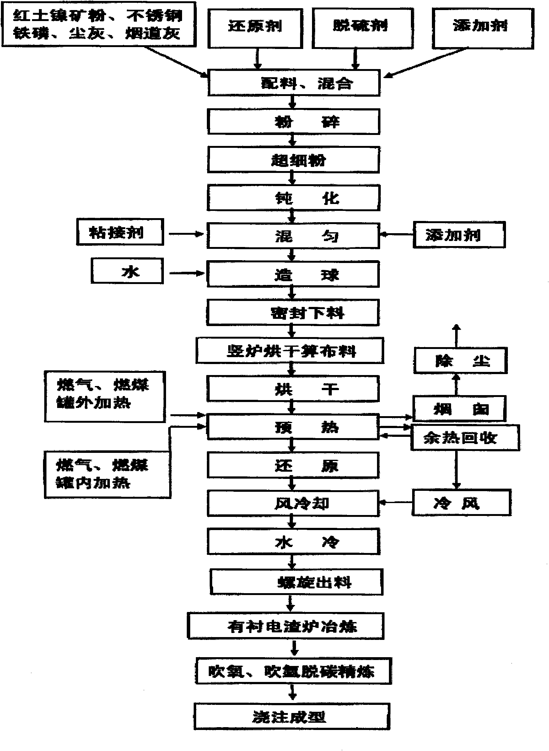
[0083] Example 1: figure 1 For the process flow diagram of the present invention, in figure 1 Among them, the process scheme to solve its technical problems is:

[0084] Mix ferronickel-containing raw materials with reducing agent, flux, and catalytic additives, and after mixing, crush them to below 200 meshes to make a mixture; then put the mixture into a ball mill for ball milling to prepare superfine powder. Carry out passivation; add water to dissolve in the catalytic additive to obtain an aqueous solution, mix the superfine powder, aqueous solution and binder together, and form a pellet after mixing evenly: ignite the fuel in the internal and external heaters in the vertical reduction furnace, and put The prepared pellets are sent into the reduction furnace through the screw feeder, and are evenly and loosely arranged on the grate of the drying bed to dry the pellets, and then roast the pellets after drying. CO, H in the roasting area and in the gas 2 React with the hy...

Embodiment 2

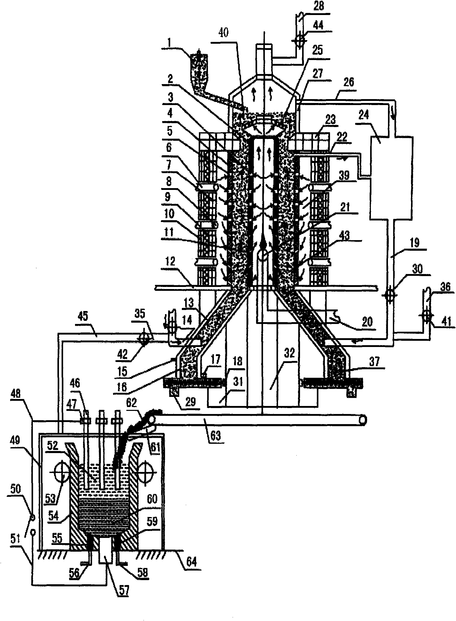
[0105] Example 2: figure 2 It is the first equipment structure diagram of the present invention, in figure 2 Among them, the equipment scheme that the present invention solves its technical problem is:

[0106] This equipment is composed of two systems of reduction equipment and smelting equipment. Wherein the reduction equipment adopts the shaft furnace body structure, and the reduction equipment includes a furnace base (12), an upper furnace body, a lower furnace body, an upper furnace cover, a drying bed furnace grate (25), a sealed feeding device (1), Purification device and waste heat circulation device, the upper furnace body is connected above the furnace base, the lower furnace body is connected below the furnace base, the upper furnace cover is connected to the upper end of the upper furnace body, and the drying bed furnace grate is located on the upper At the upper end of the furnace body, the purification device is connected with the upper furnace body and the l...
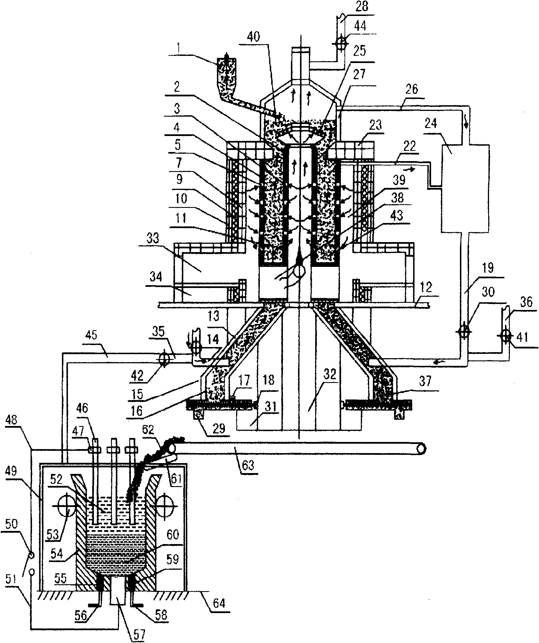
Embodiment 3

[0123] Example 3: image 3 It is the second equipment structure diagram of the present invention, in image 3 Among them, the upper furnace body in the reduction equipment includes an inner heating tank 2, a reducing gas outlet 3, an outer heating reduction tank 4, a heating air inlet 5, a refractory brick 7, a refractory fiber 9, a reduction furnace shell 10, and internal and external heating Tank air inlet 11, coal-fired combustion chamber 33, slag discharge chamber 34, internal heating channel 38, heating chamber 39, roasting reduction zone 43, reduction furnace shell, refractory brick layer, external heating reduction tank and internal heating tank are set in sequence , the reduction furnace shell is located at the outermost layer, the inner heating tank is located at the innermost layer, the coal-fired combustion chamber 33 and the slag discharge chamber 34 are located at the lower end of the upper furnace body, and the internal heating channel 38 is located at the inner ...


PUM


Abstract

The invention relates to a process and a device for smelting ferronickel and nickel-containing molten iron by using lower-nickel materials, which belongs to metallurgical industry steel-making raw material. The process comprises the following steps: mixing ferro nickel containing raw materials with reducing agent, solvent and catalyst to prepare ultra fine powder, mixing to make pelletizing materials, sending the pelletizing materials into a reducing furnace, obtaining chromium irons pellets after the reduction reaction, and directly adding reduced pellets into an lining electroslag furnace for being smelted into ferro nickel alloy or the nickel-containing molten iron. The device comprises an internal-external heating vertical reducing furnace, a lining electroslag furnace and a residual heat recovery system. The invention has the advantages that: firstly, the reduction temperature is low, the speed is high, the energy consumption is reduced, the production cost is lowered, the production efficiency is high, and the uniformity of the quality is good; secondly, the degree of mechanization is high, the procedure is simple, the yield is large, the mass production can be performed; thirdly, the waste of raw materials is reduced, the environment pollution is lowered; fourthly, the source of raw materials adopting nickel oxide ore or nickel-containing waste, the cost is low; fifthly, the waste resource can be recycled so as to save the resource consumption; and sixthly, the high-temperature pellets are directly smelted by adopting the lining electroslag furnace, the heat efficiency is high, the energy consumption is low, the material purity is high and the quality is good, and the device is simple with less investment.

Description

technical field [0001] The invention belongs to the field of nonferrous metal metallurgy, and particularly relates to a process for smelting ferronickel and molten iron containing nickel with low-nickel-containing materials, and equipment for realizing the process. Background technique [0002] Nickel is an important strategic metal and an excellent corrosion-resistant material. Nickel is not only the basic material for making nickel alloys, but also an alloying element in other alloys (iron, copper, aluminum-based alloys, etc.). Nickel is mainly used in the metallurgical industry and is an important alloying element in the production of stainless steel, special steel, high-temperature alloys, precision alloys and heat-resistant alloys. Nickel also has a wide range of applications in the fields of electroplating, magnetic materials, electronics, electrical appliances, electromagnetics and sensors, oxygen storage alloys, shape memory alloys, national defense and aviation, aer...

Claims


Application Information

Patent Timeline
Patent Type & Authority Applications(China)
IPC IPC(8): C21B13/02C22B1/242C22B9/00
Inventor 丁家伟
Owner 丁家伟
Why Eureka
Try Eureka