

Carbon Coated Magnetic Nanoparticles and Their Use in Separation Processes
a technology of magnetic nanoparticles and carbon coating, which is applied in the direction of separation processes, magnetic bodies, cellulosic plastic layered products, etc., can solve the problems of slowing down the movement of particles, increasing the overall particle diameter, and reducing the overall particle magnetization
- Summary
- Abstract
- Description
- Claims
- Application Information
AI Technical Summary
Benefits of technology
Problems solved by technology
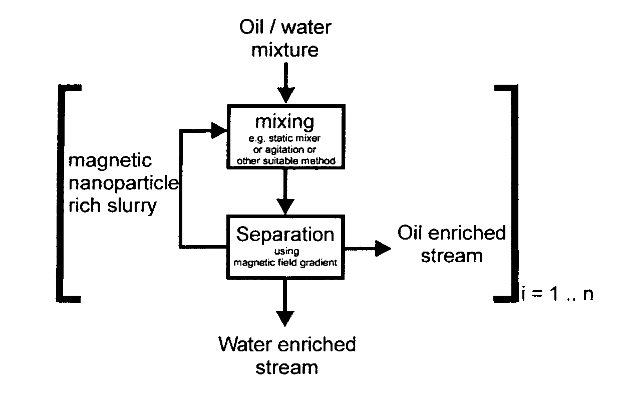
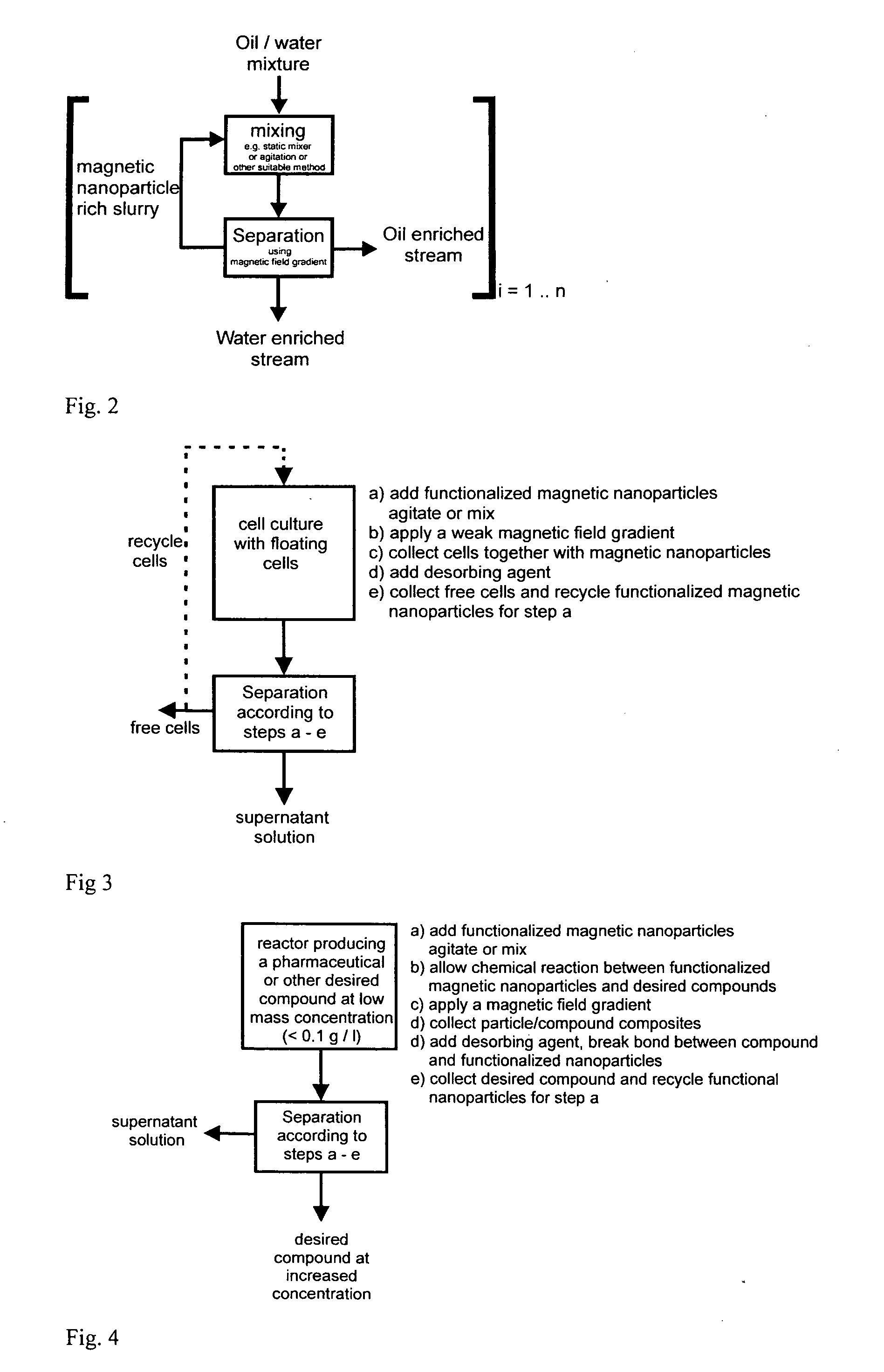
Method used
Image

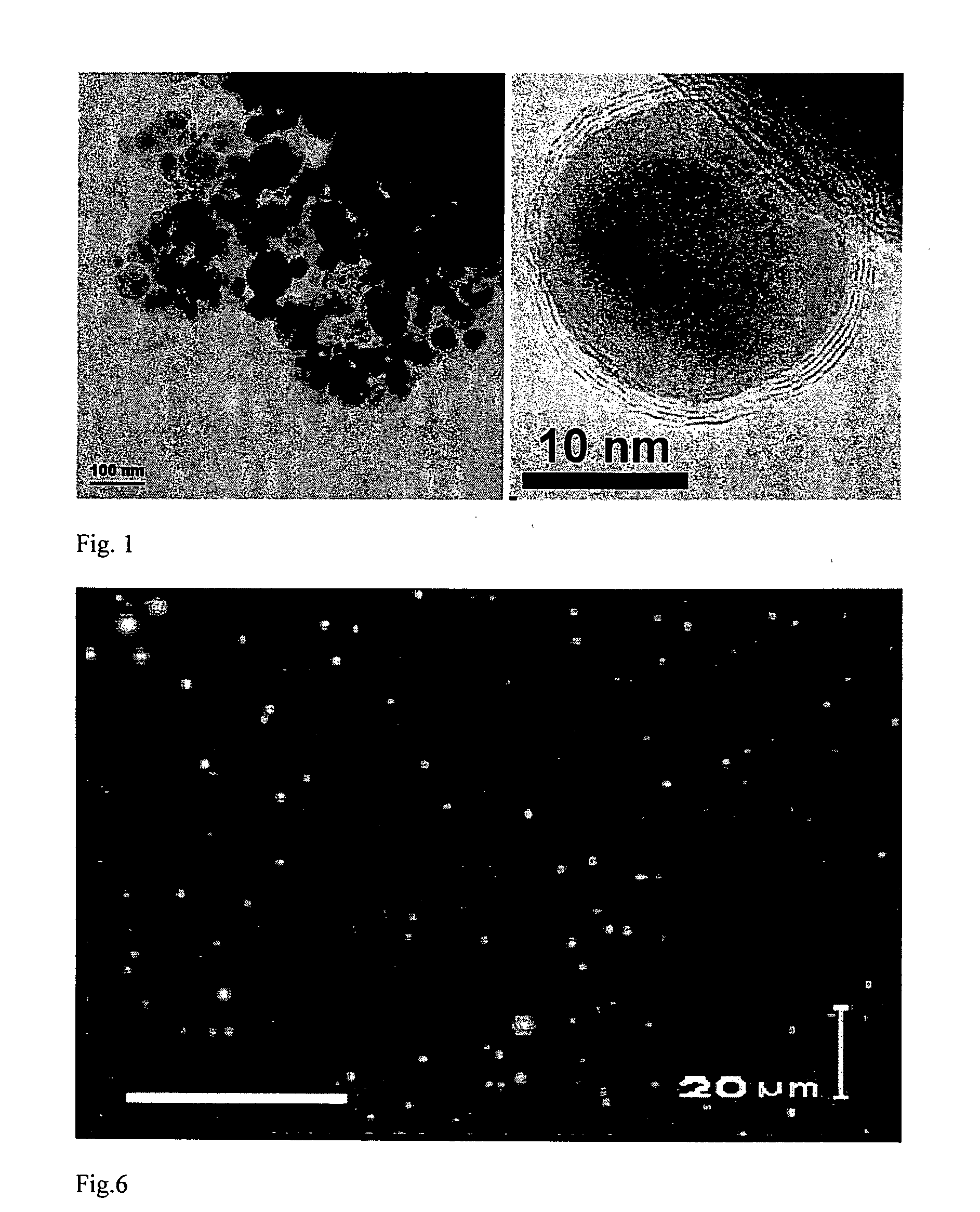
Examples
example 1.1
Preparation of Oleophilic Nanoparticles (Co / C)
[0170]Cobalt 2-ethylhexanoate in mineral spirits (Aldrich, 65 wt % Co) was diluted 2:1 with tetrahydrofurane prior to use. A spray nozzle was placed in a glove-box fed with nitrogen (PanGas, 5.0) which was recirculated by a vacuum pump (Busch, Seco SV1040CV) at about 20 m3 / h. CO2 and H2O were continuously removed from the recycle stream using two adsorption columns, packed with zeolite 4A and 13× (Zeochem), respectively. To avoid the accumulation of CO, NO and other impurities in the glove-box atmosphere a purge gas stream continuously passed the box. A sinter metal tube (GKN Sintermetalle, inner diameter 25 mm) surrounding the flame allowed radial inflow of an reactive carbon depositing gas (PanGas, Acetylene, tech 5 l / min diluted with N2, 25 l / min). A mass spectrometer (Balzers, GAM 400) was applied for the detection of the gas concentrations of H2, N2, CO2, NO, NO2 and O2. A separate data acquisition and control unit allowed controlli...
example 1.2
Chlorine Functionalization of Carbon Coated Cobalt Nanoparticles (Functionalized Co / c)
[0172]4 mmol p-chloraniline (Fluka, tech.) was dissolved in 5 g water and 0.16 g concentrated hydrochloric acid. The mixture was cooled in an ice-bath and a cold solution of 0.04 g sodium nitrite (Fluka p.a.) in 3 ml of water was added. The reactant mixture was added to 100 mg of the nanopowder (from example 1.1) in 2 ml of water. Following agitation in an ultrasonic bath during 15 minutes, the magnetic particles were separated from the supernatant by a large neodymium based magnet (1×1×1 cm) and washed 3 times with water, 3 times with hexane and 3 times with ethyl acetate. Each washing step consisted of dispersing the particles in the solvent, agitating the mixture in an ultrasonic bath during 3 minutes and separating the particles from the fluid phase by the use of a magnet. The purified magnetic material had a chlorine loading (as determined by quantitative microanalysis) of 1.1 wt %. The materi...
example 1.3
Nitro Functionalization of Carbon Coated Cobalt Nanoparticles
[0173]As-prepared carbon coated cobalt nanoparticles (150 mg, example 1.1) were suspended in a solution of 1 wt % SDS (sodium dodecyl sulfate) in water (10 ml) by the use of a ultrasonic bath (7 minutes). 4-nitrobenzenediazonium tetrafluoroborate (0.3 mmol) was added to the suspension and the mixture was left to react in the ultrasonic bath for 15 minutes. The reaction was stopped by removing the magnetic nanobeads from the reaction mixture by the use of a commercial neodymium based magnet. Washing was preformed similarly to the preparation of chloro functionalized nanobeads (water 3×, acetone 3×) and the particles were subsequently dried in vacuo at 60° C. The purified magnetic material had a nitro loading (as measured by quantitative microanalysis) of 0.1 mmol per gram. The IR absorbance spectrum of the material (5 wt % in KBr, Diffuse reflectance IR spectroscopy) showed characteristic nitrobenzene peaks (1595, 1520, 135...
PUM
| Property | Measurement | Unit |
|---|---|---|
| core diameter | aaaaa | aaaaa |
| diameters | aaaaa | aaaaa |
| specific surface area | aaaaa | aaaaa |
Abstract
Description
Claims
Application Information