Methods for removing contaminants from aqueous solutions using photoelectrocatalytic oxidization

a technology of photoelectrocatalytic oxidation and aqueous solutions, which is applied in the nature of treatment water, contaminated groundwater/leachate treatment, multi-stage water/sewage treatment, etc., can solve the problems of recirculation aquaculture, unfavorable economic recirculation, and more cost effective production of food fish in ponds and other open systems. , to achieve the effect of improving the performance of the photoelectrocatalytic oxid

Inactive Publication Date: 2011-07-28
WISCONSIN ALUMNI RES FOUND
View PDF21 Cites 46 Cited by
  • Summary
  • Abstract
  • Description
  • Claims
  • Application Information

AI Technical Summary

Benefits of technology

[0058]In another exemplary embodiment of the photoelectrocatalytic oxidation device, the lamp is adapted to emit an irradiation intensity in the range of 1-500 mW / cm2. The irradiation intensity varies considerably depending on the type of lamp used. Higher intensities improve the performance of the photoelectrocatalytic oxidation (PECO) device. The intensity can get so high that the system is swamped and no further benefit is obtained. That value depends upon the distance between the light and the photoanode.

Problems solved by technology

Fish sensitivity to ammonia and nitrite toxicity is a major factor limiting expansion of an environmentally sustainable aquaculture industry reliant on water recirculation technology.
At present, however, it is more cost effective to produce food fish in ponds and other open systems due to the high cost of building and operating complex biofiltration units, which are currently required for effective recirculation systems.
Currently, however, recirculation aquaculture is generally unfavorable economically primarily because of the high costs of constructing and operating the complex systems required for water circulation, solids capture, oxygenation, and nitrogenous waste removal.
Nitrogenous waste removal is particularly problematic.
Disadvantages of biofilters include a high concentration of nitrates, a compromise between fish and bacteria for optimal growing conditions (e.g., temperature), and bacterial growth that clogs filter pores and reduces filtration efficiency.
New biofilters take 4-6 weeks to become operational, and, for this reason, biofilters cannot be used intermittently.
Still other disadvantages include disturbances such as adding more fish or overfeeding fish that lead to spikes in ammonia, and difficulty in treating sick fish with antibiotics which may also kill beneficial nitrifying bacteria populations on the biofilters.
Optimization is difficult because aquaculture biofiltration systems require good growing conditions for both the fish and bacteria.
However, optimal temperatures for fish growth may be suboptimal for nitrifying bacteria.
Existing biofiltration systems used in aquaria and other aquaculture systems have numerous other limitations.
For example, autotrophic nitrifying bacteria and competing heterotrophic bacteria colonize within biofilters clogging filter pores and reducing nitrification efficiency.
Therefore, current systems cannot filter intermittently.
Even minor disturbances (such as tank cleaning, overfeeding, or adding new fish) can disrupt delicate nitrifying bacteria population equilibrium leading to ammonia spikes.
Sick fish cannot be treated with antibiotics because antibiotics kill nitrifying bacteria.
Such limitations associated with biofiltration systems curtail the production of aquatic organisms in water reuse systems.
Autotrophic nitrifying bacteria and heterotrophic bacteria can colonize the biofilters, which clog filter pores and reduce the efficiency of nitrification.
Biofilters are difficult to clean without reducing the beneficial bacterial populations.
Even minor disturbances, such as tank cleaning, overfeeding, or adding new fish, can disrupt the delicate equilibrium of the nitrifying bacteria populations leading to spikes in ammonia.
Such problems increase maintenance time and costs in all systems as well as salt disposal problems associated with seawater systems.
Nitrogenous waste removal in open systems is particularly problematic.
In general, nitrification is the rate-limiting step in biological nitrogen removal processes.
Maintaining adequate levels of nitrifiers is a significant problem in biological removal processes.
Bacterial metabolites associated with and produced by biofilters can adversely affect physiological responses of certified disease-free fish strains.
Thus, there is an absence or shortage of certified disease-free zebrafish.
Electrochemical methods produce little or no sludge, can work with high or variable pollutant concentrations, and are generally unaffected by the presence of impurities.
However this has not normally been possible using electrochemical systems.
Such systems are also substantially unaffected by the presence of impurities.
When ammonia is chlorinated, final products may include toxic chlorine gas and explosive nitrogen trichloride.
Moreover, the electrochemical method may require high levels of energy, and chloride ions must be added to the system for the method to work.
However, such electrodes are very expensive.
Other alternatives to biological filtration, such as ammonia stripping and ion exchange, are impractical or uneconomical in most circumstances.
Groundwater pollution or contamination may be caused by human activities such as application of fertilizers, herbicides, and pesticides to crops, and / or originate from industrial waste disposal, accidental spills, leaking fuel storage tanks, dumps and landfills.
Large-scale use and leaking of underground fuel storage tanks, for example, has resulted in groundwater contamination by gasoline and fuels.
Additionally, groundwater contamination may occur naturally such as, for example, by arsenic.
Moreover, many of these organisms produce cysts that may exist in water.
Organisms and other wastes may also contaminate ballast water used in ships for stability and trim.
Subsequent release of the ballast water can result in the introduction of exotic and non-native species and may cause detrimental impact on the environment and local economy.
In addition to high cost, some of these alternative remediation technologies result in the formation of other contaminants at concentrations higher than their recommended limits.

Method used


Image

  • Methods for removing contaminants from aqueous solutions using photoelectrocatalytic oxidization
  • Methods for removing contaminants from aqueous solutions using photoelectrocatalytic oxidization
  • Methods for removing contaminants from aqueous solutions using photoelectrocatalytic oxidization

Examples


example 1

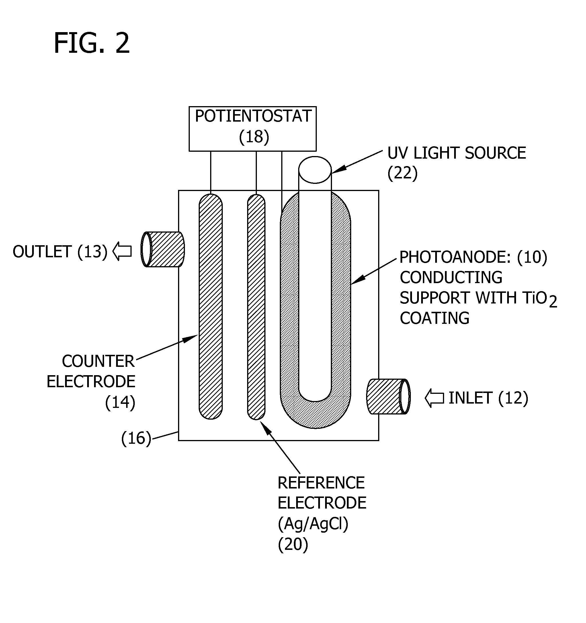
[0211]Static test system. The photoanode was rolled into the cylinder and disposed into a 300 ml glass beaker. The UV light source contained in a quartz sleeve (32 mm ID, 35 mm OD, 15 cm long) was disposed in the center of the beaker. The cathode (which was the counter electrode) comprised a Ti wire (0.5 mm diameter and 15 cm long from Goodfellow Corp., Oakdale, Pa.). The reference electrode comprised a silver wire (0.5 mm diameter and 15 cm long from Goodfellow Corp., Oakdale, Pa.).

[0212]The cathode and reference electrodes were attached to the outer wall of the quartz sleeve with silicon glue running parallel and separated by 2 cm. The light source was a 9-watt, low-pressure mercury vapor lamp (Jebo Corp., Taiwan, China) that emitted ultraviolet germicidal irradiation (UVGI) at a primary wavelength of 254 nm. The distance from the light to the photoanode was approximately 5 cm. Four identical static PECO systems were prepared for replicate testing.

[0213]Each experiment, except the...

example 2

[0220]Chemicals. TiO2 coatings on photoanodes were made from titanium isopropoxide (Aldrich Chemical, 97%) and nitric acid (Aldrich Chemical, American Chemical Society reagent grade). NH4Cl and NaCl were obtained from Fisher Scientific (Fairlawn, N.J.). NaNO3 and NaNO2 standards were obtained from SPEX Certiprep (Metuchen, N.J.). NH4+ / NH3 was measured using commercial kit reagents for indophenol method. All chemicals were used without further purification. All solutions were prepared with ultrapure water (18.1 Mω cm) from a NANOpure UV system (model 07331, Bamstead / Thermolyne, Dubuque, Iowa).

[0221]Composite Photoanode Preparation. The photoanode substrate material was annealed titanium foil 0.05 mm thick (99.6+% purity, Goodfellow Cambridge Ltd). Foils were cut to size for the experimental cell and pre-heated to remove organic contaminants by firing for 300° C. for 3 h. Suspensions of titanium dioxide were prepared using processing methods. (See Candal et al., 1998). Photoanodes wer...

example 3

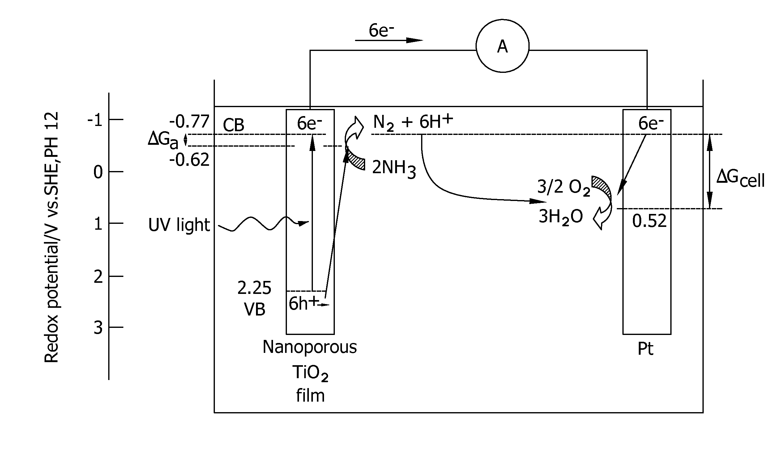
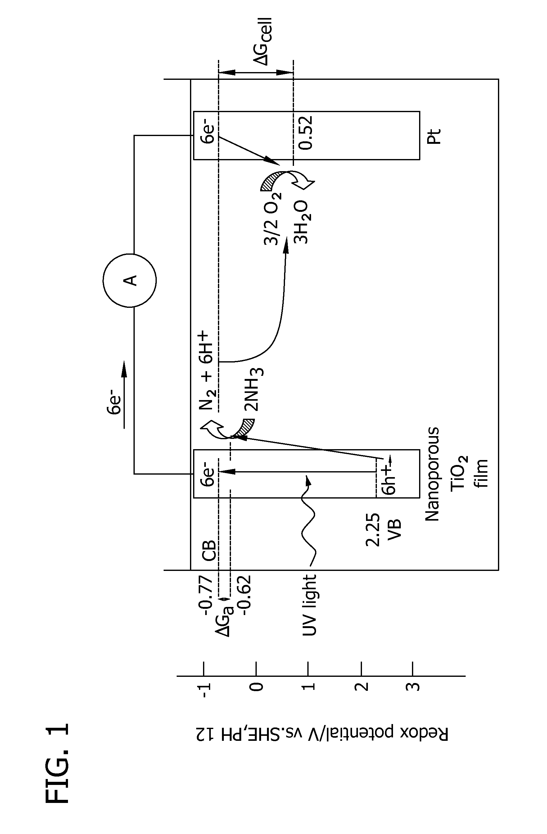
[0229]Fifteen minute chronoamperometry experiments were conducted to analyze the effects of salinity, light intensity, and applied potential on the photoelectrocatalytic oxidation of aqueous NH4+ / NH3. TiO2 coatings were applied to Ti foil by dip coating and sintered at 400° C. to sinter a nanoporous photocatalytic surface. Photoanodes were used in combination with a platinum wire counter electrode and saturated calomel reference electrode (SCE) to test ammonia removal and nitrate / nitrite production at initial ammonium / ammonia concentration 0.54 mg NH4+ / L, initial pH 7 in a well-mixed static reactor with compressed air sparged into solution. At applied potentials greater than −0.4 V, NH4+ was totally removed in ten minutes and less than 3% of the initial NH4+ was converted to NO3− and none was converted to NO2−.

[0230]Chloride ions are present at 0.25 g NaCl / L or greater so that ammonia oxidation occurs. Conversion of NH4− and NO3 to N2 reached 40-41% at lower salinities, but at 31 g ...


PUM

PropertyMeasurementUnit
pore diameteraaaaaaaaaa

Abstract

A photoelectrocatalytic oxidizing device having a photoanode being constructed from a conducting metal such as Ti as the support electrode. Alternatively, the photoanode is a composite electrode comprising a conducting metal such as Ti as the support electrode coated with a thin film of sintered nanoporous TiO2. The device is useful in methods for treating an aqueous solution such as groundwater, wastewater, drinking water, ballast water, aquarium water, and aquaculture water to reduce amounts of a contaminant. The method being directed at reducing the amount and concentration of contaminants in an aqueous solution comprising providing an aqueous solution comprising at least one contaminant, and, photoelectrocatalytically oxidizing the contaminant, wherein the contaminant is oxidized by a free radical produced by a photoanode constructed from an anatase polymorph of Ti, a rutile polymorph of Ti, or a nanoporous film of TiO2.

Description

CROSS REFERENCE TO RELATED APPLICATIONS[0001]This application claims priority to and benefit of U.S. patent application Ser. No. 12 / 369,219 filed Feb. 11, 2009, which claims priority to and benefit of U.S. Provisional Patent Application Ser. No. 61 / 027,622 filed Feb. 11, 2008, which is hereby incorporated herein by reference in its entirety.[0002]This application is related to commonly-owned U.S. patent application Ser. No. 11 / 932,741, which is hereby incorporated by reference.[0003]This application is related to commonly-owned U.S. patent application Ser. No. 11 / 932,519, which is hereby incorporated by reference.STATEMENT REGARDING GOVERNMENT INTEREST[0004]This invention was made with government support under 2007-33610-18003 awarded by the USDA / CSREES. The United States Government has certain rights in the invention.BACKGROUND OF THE DISCLOSURE[0005]The present disclosure generally relates to the removal of contaminants from aqueous solutions. Particularly, methods are disclosed f...

Claims


Application Information

Patent Timeline
Patent Type & Authority Applications(United States)
IPC IPC(8): C02F1/461C02F1/467
CPCA01K63/04A01K61/00A01K61/13C25B11/031Y02W10/37Y02A40/81A01K63/042C02F1/283C02F1/325C02F1/4672C02F1/725C02F9/00C02F2101/101C02F2101/103C02F2101/12C02F2101/14C02F2101/16C02F2101/166C02F2101/18C02F2101/20C02F2101/203C02F2101/206C02F2101/22C02F2101/30C02F2103/00C02F2103/008C02F2103/06C02F2103/20C02F2201/322C02F2201/46105C02F2303/04C02F2305/023C02F2305/10
Inventor BARRY, TERENCE P.TOMPKINS, DEAN T.ANDERSON, MARC A.ZELTNER, WALTER A.
Owner WISCONSIN ALUMNI RES FOUND
Why Eureka
Try Eureka