This process has the following major drawbacks: the first drawback is large consumption of
sulfuric acid; the second drawback is that the
slag phosphogypsum cannot be used effectively, and
sulfuric acid, phosphoric acid and soluble fluorides entrained therein are all soluble in water, and rain wash of the
slag piled in the nature is apt to cause serious
pollution to the environment; the third drawback is that the
resultant phosphoric acid contains higher content of impurities and is generally only used to produce
fertilizer; and the fourth drawback is that high-grade
phosphate ore must be used to ensure economy of the product.
The hot-process production of phosphoric acid has the following main drawbacks: the first drawback is large consumption of electrical energy; the second drawback is that gas discharged out of the ore-
smelting electric furnace, from which P4 is already separated, still entrains a large amount of fluorides (existing in the form of SiF4 and HF) and a small amount of un-deposited gas P4, which causes serious
pollution to the atmospheric environment; the third drawback is that gas containing a large amount of CO is directly burnt and exhausted, which causes large waste of energy; the fourth drawback is that high-grade
phosphate ore needs to be used to ensure economy of the production.
1. A
rotary kiln is an apparatus with a
kiln body rotating at a certain speed (0.5 r / min-3 r / min), and it is advantageous in continuously performing mechanical turn and mixture of a
solid material fed into the
kiln to ensure uniformity of heat reception of the
solid material at all locations in the kiln. However, the
solid material in the kiln must bear a mechanical frictional force resulting from movement of the material. If the strength of the material is smaller than the received mechanical frictional force, the material can be easily destroyed. A basic principle of the KPA process proposed by ORC corporation is to co-
grind the phosphate ore, the silica and the carbonaceous
reducing agent (
coke powder or
coal powder) so that 50%-85% of the co-ground materials pass 325 mesh, and then produce them into
pellets, the three kinds of substances must be closely copolymerized into a whole so that the mixture does not melt at the carbon thermal reduction temperature of the phosphate ore under the condition the CaO / SiO2
mole ratio in the mixture is 0.26-0.55, and meanwhile carbon reduction of the phosphate ore can be performed smoothly. However, since the
reducing agent carbon is added to the material
pellets used in the process, carbon goes through quick oxidization reaction with
oxygen in air at a temperature greater than 350 to produce CO2. If a conventional method of consolidating
pellets at a high temperature at a chain grate in the
metallurgical industry is employed, the reducing carbon in the pellets will be all oxidized, the pellets entering the
rotary kiln will lose the
reducing agent, carbon thermal reduction reaction of the
phosphorus naturally cannot be performed, and the process fails as a result. If only the
bentonite is added as a bonding agent of the pellets to perform
drying and
dehydration at a temperature less than 300, an anti-pressure strength of the pellets is only about 10 KN per ball, with a falling strength e
metallurgical industry is employed, the reducing carbon in the pellets will be all oxidize water in its substance structure to adjust a
moisture content release speed during the
drying of the pellets and improve a burst temperature of the pellets during the
drying, and
bentonite itself does not play a remarkable role in improving the strength of the pellets. After such pellets are fed into the
rotary kiln and before the rotary kiln temperature value reaches 900, since the pellets entering the kiln cannot bear the mechanical frictional force resulting from movement of material balls in the pellets, a lot of said pellets are pulverized, and thereafter the phosphate ore
powder, silica powder and carbonaceous reducing agent forming the pellets will separate, the phosphate ore powder after pulverization causes failure of reduction of phosphorus as it cannot get in
close contact with carbonaceous reducing agent. More seriously, once the phosphate ore powder separates from silica powder, its
melting point abruptly falls below 1250. When such powder-like phosphate ore passes through a high-temperature reducing area (with a material layer temperature of 1300 or so) of the rotary kiln, it will totally changes from solid phase into a
liquid phase, and thereby adheres to a liner of the rotary kiln to form high-temperature
ringing of the rotary kiln, which hinders normal rotation of the materials in the rotary kiln so that a majority of materials added into the rotary kiln overflows from the rotary kiln from a feeding end of the rotary kiln, high-temperature reduction of phosphorus cannot be achieved and the process fails. It can be seen that the raw materials entering the kiln have their intrinsic drawbacks, any industrialized, large-scale or commercialized application of the above-mentioned KPA technology has not yet been witnessed so far.
2. Regarding the KPA process with the phosphate ore pellets with carbon being added, a
solid material area below a material layer in the rotary kiln belongs to a reduction zone, and a gas flow area of the rotary kiln is above the material layer and belongs to an oxidization zone, the feed pellets are added from a kiln
tail of the rotary kiln and discharged out of a kiln head of the rotary kiln by virtue of its own gravity and a frictional force resulting from rotation of the rotary kiln, a burner for burning fuel in the rotary kiln is mounted at the kiln head of the rotary kiln, fume resulting from the burning is introduced out by a blower at the kiln
tail, a micro negative pressure is maintained in the rotary kiln, and the gas flow is opposite to a movement direction of the materials. Since there is not a mechanical isolation area between the reduction zone (
solid material layer area) and the oxidization zone (the gas flow area above the solid material layer area of the rotary kiln) of the rotary kiln, the material balls exposed on the surface of the solid material layer area and O2, CO2 in the gas flow in the oxidization zone are subjected to convective
mass transfer; on the one hand, this causes the reducing agent in the material balls to be partially oxidized before the material balls are heated by the gas flow
heat transfer to the carbon reduction temperature of the phosphate ore so that the material balls are not sufficiently reduced due to shortage of carbonaceous reducing agent in the reduction zone of the rotary kiln; more seriously, the material balls exposed to the surface of the material layer at the high-temperature area of the rotary kiln is further subjected to
chemical reaction with P2O5 already generated from reduction in the kiln gas to produce
calcium metaphosphate,
calcium phosphate and other metaphosphates or phosphates, thereby causing the phosphorus already reduced into the
gas phase to return to the material balls again and form a layer of white crust rich in P2O5 on the surface of the material balls, the layer of crust generally having a thickness of 300 μm-1000 μm, the content of P2O5 in the layer of crust
topping 30%; as a result, P2O5 transferred from the material balls to the
gas phase does not exceed 60%, which cause a
lower yield ratio of P2O5 in the phosphate ore and thereby causes waste of mineral resources and large rise of the phosphoric
acid production cost so that the above KPA process losses value in respect of commercial application and industrial spread. Researchers desire gas volatized from the material layer to isolate the reduction zone from the oxidization zone in the rotary kiln, but industrial experiments performed in a rotary kiln with an inner
diameter 2 m show that the phenomena of white crust rich in P2O5 on the surface of the pellets still cannot be avoided.
Due to the above-mentioned technical drawbacks, it is still very difficult to use the KPA process proposed by ORC corporation in large-scale industrial application and practice to produce phosphoric acid.
However, increase of the
filling rate of the rotary kiln allows the material balls to bear larger mechanical frictional force in the rotary kiln, thereby causing a larger proportion of pulverization of the material balls in the rotary kiln, and forming more substances with a
melting point lower than the phosphate ore carbon thermal reduction temperature so that the high-temperature
ringing of the rotary kiln becomes quicker and more serious and earlier failure of the process is caused.
In addition, the volatile matter generated by added small amount of petrol
coke is not sufficient to produce sufficient gas and it is difficult to form an effective
isolation layer between the solid material layer of the rotary kiln and the gas flow area in the rotary kiln.
If an excessive amount is added, the materials in the rotary kiln will entrain a large amount of fuel so that in a slag ball cooling
machine in the subsequent process, the redundant fuel is confronted with the air for cooling the slag balls and burns rapidly, a large amount of heat resulting from the burning not only increases the difficulty in cooling the high-temperature slag balls exiting the rotary kiln but also substantially improves the production cost of the process and makes implementation of the commercialized and large-scale application of the process impossible.
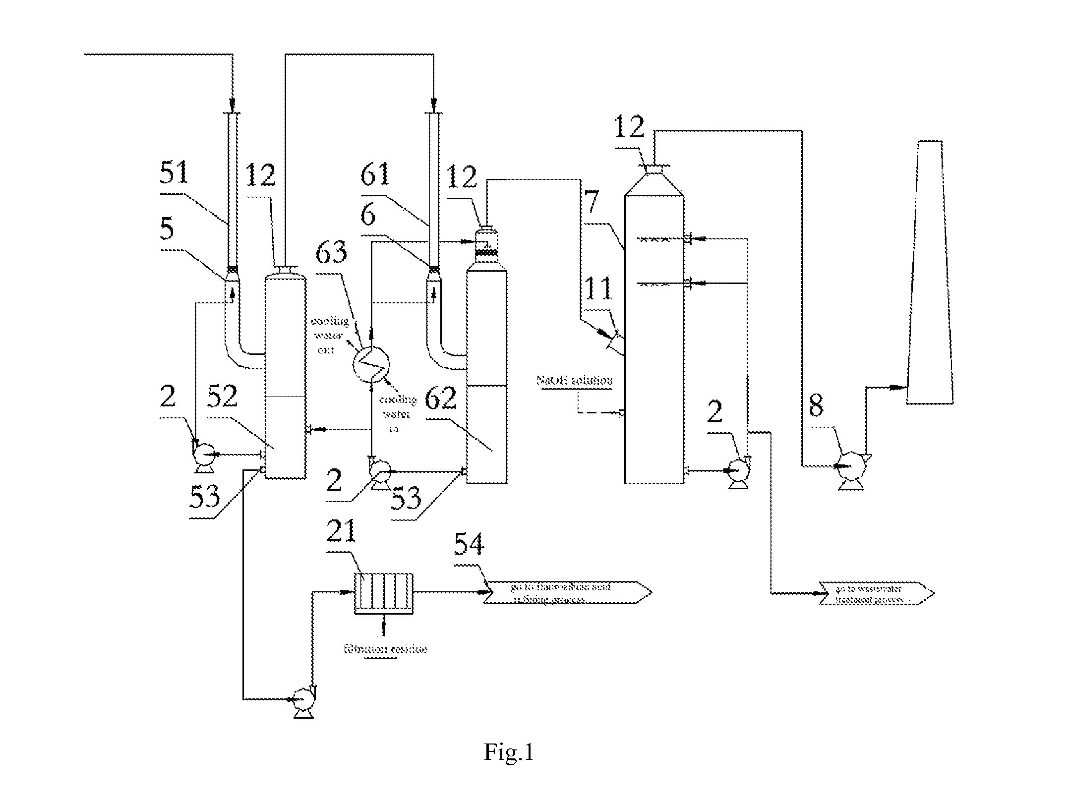
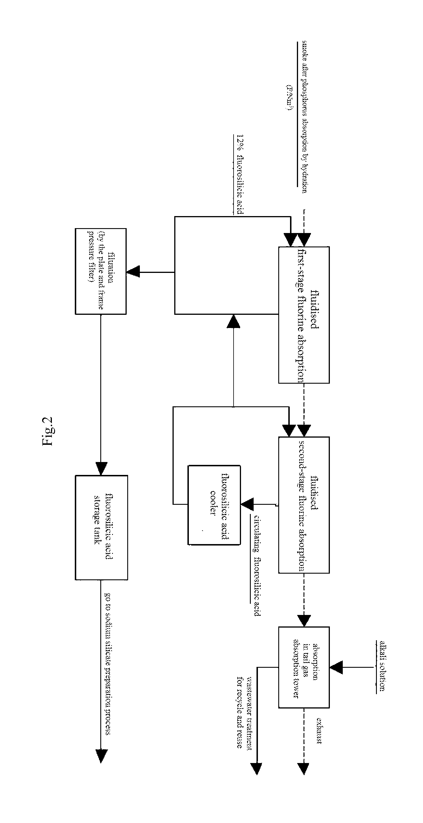
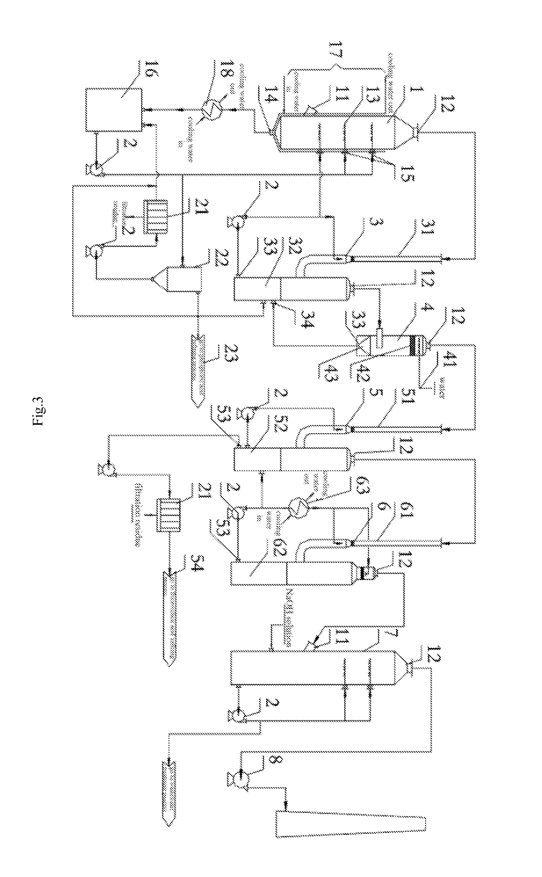
However, KPA process still presents a series of technical problems and some exist in the process for absorption of phosphorus by hydration and fluorine recovery in KPA.
Using the method for absorption of phosphoric acid in hot process may cause the following problems: firstly, the lower production of smoke produced in hot process results in a lower flow rate of smoke in the corresponding equipment, and if this method for absorption of phosphoric acid in hot process is used in KPA process, the equipment
system in KPA process will reach a quite
large size, which may lead to be a complex structure and an increased cost of investment and operating; secondly, the variable impurities in smoke produced in KPA require a spraying acid with a higher
corrosion, and the process and device for absorption of phosphoric acid need to be further improved to prevent the solid impurities in acid from blocking the equipments and pipeline; more importantly, the fluorine-containing substance (exists in form of SiF4 and HF) in smoke exiting the kiln in KPA which is harmful to human needs to be recovered to avoid
contamination of environment

