System and method for producing silicon-containing product by utilizing silicon mud byproduct of cutting silicon material with diamond wire

Active Publication Date: 2022-09-13
CHU XI
View PDF2 Cites 0 Cited by
  • Summary
  • Abstract
  • Description
  • Claims
  • Application Information

AI Technical Summary

Benefits of technology

[0006]In view of the shortcomings of the prior art, the diamond wire cutting silicon raw material recycling has a long process flow, complicated process, high energy consumption and low effective utilization, the present invention utilizes the fact that each particle (Si) surface having a thick oxide layer generated during cutting (The characteristics of SiO2) are disproportionated in a vacuum or non-oxidizing atmosphere to cause the surface oxide layer to react with the elemental silicon in close proximity to it to form sublimation of the silicon monoxide and to separate from the surface of the silicon particle to achieve the purpose of removing the surface oxide layer. Therefore, it is possible to further carry out a physicochemical reaction with a metal, a halogen gas, a hydrogen halide gas or hydrogen to further convert the silicon sludge into elemental silicon, silicon alloys, and a halosilanes, thereby producing a high value-added silicon-containing industrial product. At the same time, it has produced more valuable silicon monoxide that can be used in many fields. The avoid the disadvantages in conventional method of removing the silicon oxide layer by pickling, adding a reducing agent, etc., with high cost, environmental pollution, and waste of silicon material.
[0007]This method does not attempt to separate and recover silicon powder from the diamond-cut silicon sludge by using different density according to the conventional method. It also eliminates the two extreme misunderstandings that the silicon powder in the diamond wire-cut silicon particle is not oxidized or completely oxidized. Instead, the diamond wire-cut silicon is directly used as a reaction raw material to prepare a silicon-containing product, which has the advantages of short process, low energy consumption, complete separation and full utilization. At the same time, the effective utilization of silicon by-products of diamond wire cutting silicon raw materials and the large-scale production of silicon monoxide are combined to realize the large-scale, high-efficiency, energy-saving, continuous and low-cost complete recycling of diamond wire cut silicon kerfs.
[0008]The use of a carbonylation technique to remove metallic impurities in silicon sludge is also of great significance. Because in the current industrial production, a large amount of transition metals such as Co. Ni, Cr and other emissions are produced, mostly in the form of industrial sludge, and sometimes the transition metal penetrates into the soil to cause greater environmental damage. The treatment of such transition metal pollution has always environmental problems, traditional methods are mostly washed by pickling, but the cost is high, causing secondary environmental pollution, and also causing waste of transition metals. In view of these issues, the present application utilizes the principle that some metals can be carbonylated, realizes the purpose of dry recovery of the transition metal and the effect of full utilization, and is a novel environmental treatment method, which can not only effectively recycle and convert metal-containing impurities, but also, can also be used to repair contaminated soil by solid hazardous waste and solve the problem of waste caused environmental pollution in industrial emissions.

Problems solved by technology

In addition, to the useful silicon powder in the 
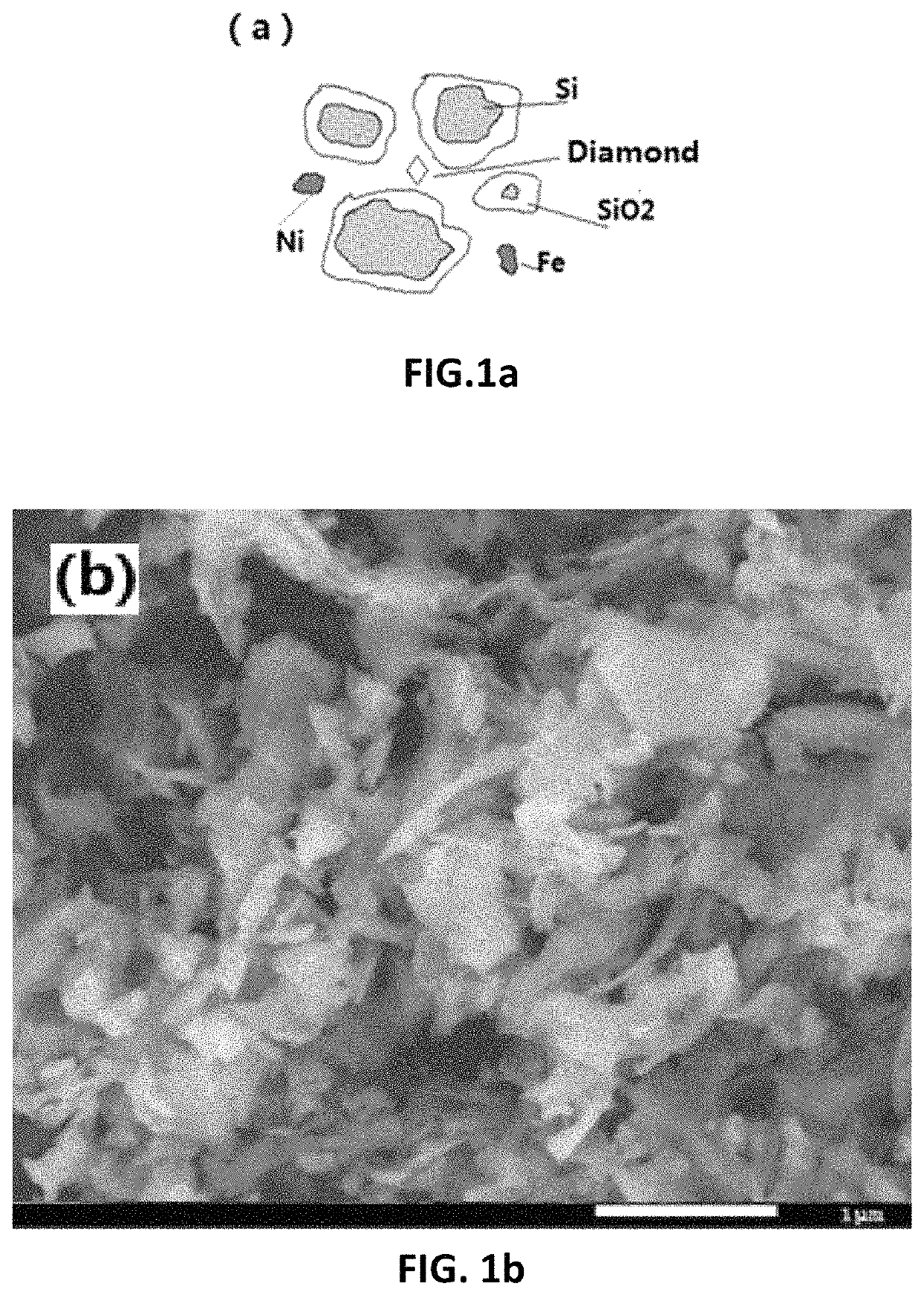
cutting liquid, there are broken diamond, resin or nickel-based alloy for fixing diamond particles on the cutting wire, and cutting wire base steel wire, pellet Subtle, different in nature, although these impurities are relatively small, only a few thousandth of the total, silica-coated silicon powder accounts for more than 99%, of which elemental silicon accounted for more than 85%, but It is still very difficult to separate the useful part of the silicon.
The avoid the disadvantages in conventional method of removing the silicon oxide layer by pickling, adding a reducing agent, etc., with high cost, environmental pollution, and waste of silicon material.
This method does not attempt to separate and recover silicon powder from the diamond-cut silicon sludge by using different density according to the conventional method.
Ni, Cr and other emissions are produced, mostly in the form of industrial sludge, and sometimes the transition metal penetrates into the soil to cause greater environmental damage.
The treatment of such transition metal pollution has always environmental problems, traditional methods are mostly washed by pickling, but the cost is high, causing secondary environmental pollution, and also causing waste of transition metals.
The collection of SiOx is carried out in the downstream tube, but as the reaction time is prolonged, the inner diameter of the tube becomes smaller and smaller, the surface area of the inner wall becomes smaller and smaller, and the collection efficiency becomes lower and lower, so that the reaction has to be terminated and the overall efficiency is low.
The traditional method of producing silicon monoxide, using high-purity silicon and high-purity silica grinding and mixing and then disproportionation at high temperature, the cost is high, the reaction can not be completely carried out, because after the particle intersection react to produce silicon monoxide, the silicon dioxide and silicon particles are no longer in physical contact, thus no further reaction.
Sometimes the transition metal penetrates into the soil to cause greater environmental damage.
Protection problems.
For silicon powder in silicon waste, general understanding of the oxidation of their surface is very limited, and no effective method has been developed to quantitatively determine the degree of oxidation.
Various chemical methods such as pickling and alkaline washing etch away the surface silica, which not only increases the cost, but also wastes the valuable oxide layer on the surface, and also causes waste and secondary pollution.
It is difficult to control the pickling and alkali cleaning.
Excessive erosion is inevitable.
Not only the oxide layer is removed but also the internal silicon is lost, which causes greater waste.
The prior art also recognizes this, so that before the drying of the silica waste, the complex multiple pickling methods are used to remove the metal components, which not only causes pollution but also depletes the silicon itself.
In this traditional process, first, the raw material cost is high, the grinding needs to consume a large amount of energy, and it is difficult to uniformly mix silicon and silica; secondly, the produced silicon monoxide is deposited in the internal wall of downstream tube of the reactor, and as the process proceeded, the internal diameter of the tube getting smaller and smaller, the collection efficiency is getting lower and lower due to the smaller surface area of the inner wall of the tube.
Finally, the material produced should be ground into fine powder before it can be added to the lithium-ion negative carbon material in order to be practically applied, all of which cause its high cost and difficult to promote on the market.
However, this protective layer has only a few nanometers of protective interior which is not further oxidized.
Iron removal prevents the formation of chlorides during the chlorination reaction, which, together with the chlorosilanes, enters the distillation system, increasing the difficulty of distillation and reducing the purity of the chlorosilanes.
Although the principle of carbonylation has been widely applied in other fields, it has not been reported in the field of treating sewage metal that is superior to the conventional method.
In the process of this application, the problem of the precise content of silicon in silicon waste is also plagued, by a long-term extensive experiment, finally we developed the method for accurately determining silicon and silicon dioxide in silicon waste.
2. Although the information of silicon oxide can be obtained by using X-ray photoelectron spectroscopy, if the surface of silicon is oxidized, it is difficult to accurately analyze the content of internal silicon.
3. Using the difference in density between silicon and silicon oxide, since the density of the two is close and the density data is greatly affected by the source of the sample, a reliable density value of the true state of silicon and silicon oxide in the sample cannot be obtained. There is also no operability;
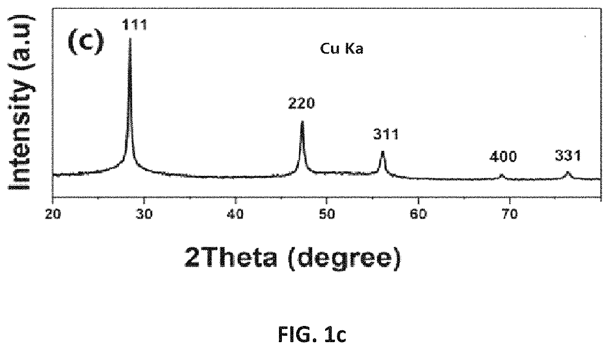
4. A large number of analyses were performed on silicon and silicon oxide by full-spectrum fitting using X-ray diffraction. Since silicon oxide has an amorphous state and there are several crystal states of silicon oxide, it is unlikely that silicon oxides in different states can be analyzed;
5. Quantitative analysis of the mixture by solid nuclear magnetic method, taking into account the measurement accuracy of NMR, for semi-quantitative analysis may get better results, such as quantitative analysis, almost impossible;
6. By comparison of various means, gravimetric analysis is a better choice.
The reactor for carrying out the disproportionation reaction; in particular, for the dried silicon sludge, since the particles are extremely fine, the fine powder is not further granulated, and it is difficult to directly use the conventional reactor type to produce.
Sometimes the transition metal penetrates into the soil to cause greater environmental damage.
The treatment of such transition metal pollution has always been environmental protection challenge.
Conventional reactors can be used after molding the powder, but metallic iron and nickel particles are difficult to completely react internally.
(1) Reactor 1 for carrying out a disproportionation reaction; the reactor is provided with a temperature control equipment (not shown). Specifically, the reactor may be an entrained flow bed, a fluidized bed, a fixed bed or a moving bed, preferably a fixed bed or an entrained bed. Since the material is fine after drying, the conventional fluidized bed reaction is difficult to control, and a large number of the reaction silicon sludge is brought downstream to cause material waste and pipe blockage, and the gas flow bed allows the material to be completely mixed with the reaction gas, greatly increasing the reaction surface.
As the reaction time is extended, the inner diameter of the tube becomes smaller and smaller, the surface area of the inner wall becomes smaller and smaller, and the collection efficiency becomes less and less effective.
The reaction has to be terminated and the overall efficiency is low.
At the same time, there is no limit to the particle size, as in conventional methods such as fluidized bed reactor there is a limitation of the particle size depending on the flow velocity of the fluidized gas, and large particles are generally cannot be prepared.
Because of this, the surface of the distributor is the surface of the substrate that is first contacted with the gas to be deposited first, so that the vent hole (spacing) of the distributor must be blocked first, and it is difficult to keep it open for a longer time.
Thermal management: Gas-solid reaction is inevitably accompanied by a large amount of heat emission and / or absorption, and these heats occur at the deposition interface.
How to effectively manage the thermal energy of the reaction interface and quickly and effectively reach the temperature required for the reaction has always been the most difficult problem in the industrial application industry.

Method used


Image

  • System and method for producing silicon-containing product by utilizing silicon mud byproduct of cutting silicon  material with diamond wire
  • System and method for producing silicon-containing product by utilizing silicon mud byproduct of cutting silicon  material with diamond wire
  • System and method for producing silicon-containing product by utilizing silicon mud byproduct of cutting silicon  material with diamond wire

Examples


example 1

on and Determination of Silicon Content of Silicon Raw Materials

[0168]The as received silicon waste material is grayish black, which mainly contains silicon powder and contains 10-30% liquid. Five 5 kg of the silicon waste material was placed in a quartz crucible and placed in an oven and dried at 110° C. for 24 hours until no volatile odorous gas overflowed to obtain a large piece of silicon waste, and then the bulk silicon waste was pulverized and repeatedly baked to 230° C. until The silicon waste was 100 mesh or less without weight loss, and finally 3943 g of dry silicon waste was obtained. All the silicon sludge prepared by this method was used as a raw material in all experiments thereafter.

[0169]FIG. 1b and FIG. 1c are scanning electron micrographs (FIG. 1b) and X-ray diffraction patterns (FIG. 1c) of the dried silicon waste in Examples 1-4 before the reaction. It can be seen that there is no other crystalline material other than silicon, but the silicon oxide on the surface ...

example 2

[0175]Take 2000 g of the dried silicon waste material obtained in Example 1, place 2000 ml of graphite crucible, put it into a vacuum induction melting furnace (Shanghai Chenhua), first evacuate to a vacuum of 10-3 torr or less, and then flush it into high-purity argon gas and heat it up to 1500° C. During the heating process, silicon monoxide is formed and volatilized. After the silicon is melted (observed through the transparent window), it is cooled to room temperature, and 1400 g of crystal silicon (including the part that cannot be separated inside the crucible) was obtained. It can't be taken out in the crucible, and the weight of the crucible is increased by 30 grams. Its appearance is similar to that of polysilicon. The composition analysis is shown in Table 1. In addition, this experiment did not dock specifically to silicon monoxide collection equipment, and at the same time, some of the silicon oxide was not completely reacted. Only 5 grams of the sample was obtained from...

example 3

[0176]As shown in FIG. 3, a 500 KW industrial melting furnace is equipped with a built-in graphite crucible of 200 liters. The top has a graphite cap. The 12-foot quartz tube is connected to a two-meter-diameter stainless steel drum with a diameter of 120 cm and then connected to a Roots blower to ensure that the stainless steel barrel has a continuous negative pressure (0.7-0.9 atm) and is externally cooled by tap water.

[0177]First, 25 kg of dry silicon powder is add to the graphite crucible (since the density of the silicon powder is lower, depending on the particle size distribution of the particles, generally 0.6-1.2 g / cc, which is much lower than the density of elemental silicon of 2.3 and the density of the melted silicon is greater than elemental silicon, up to 2.56). The induction heating element 2 equipment was started to heat up to 1500-1600° C. in 2 hours. When there is no silicon monoxide to overflow, heating was stopped, and then add 125 kg of dry silicon powder to the ...


PUM

PropertyMeasurementUnit
temperatureaaaaaaaaaa
melting pointaaaaaaaaaa

Abstract

The present application provides a system and method for producing a silicon-containing product by using a silicon sludge, which is produced by a cutting silicon material with a diamond wire. The method utilizes a high oxide layer on the surface of a silicon waste particle produced during diamond wire cutting. The surface oxide undergoes a disproportionation reaction with adjacent internal elemental silicon to form silicon monoxide, which is removed in a vapor to achieve a physical chemical reaction with a metal, a halogen gas, a hydrogen halide gas or hydrogen to form silicon-containing products of higher added value. The process realizes the large-scale, high-efficiency, energy-saving, continuous and low-cost complete recycling of silicon waste produced by diamond wire cutting of silicon material.

Description

[0001]This application claims the Chinese Patent Application No. CN201710206493.8, which is submitted to the China Patent Office on Mar. 27, 2017, is entitled “A Method and System for Recycling Silicon by-products of Silicon Diamond Wire Cutting”. The entire contents of this application are hereby incorporated by reference herein by reference. The application also claims to be submitted to the Chinese Patent Office on May 5, 2017 as CN201710361112.3, entitled “A Reactor and Method for Producing Silicon monoxide and its application in Lithium Ion Battery Anode Material Produced Thereof” The priority of the Chinese Patent Application, the entire contents of which is incorporated herein by reference.TECHNICAL FIELD[0002]The present application relates to recycling kerfs produced during silicon diamond cutting process, and more particularly to a method, equipment and system for producing silicon-containing products by using a silicon sludge which is produced by a diamond wire cutting of...

Claims


Application Information

Patent Timeline
Patent Type & Authority Patents(United States)
IPC IPC(8): C01B33/18C01B32/97C01B33/023C01B33/037
CPCC01B33/182C01B32/97C01B33/023C01B33/037H01M4/386H01M10/0525C22B7/001C01B33/10C01B33/107C01B33/10726C01B33/10736C01B33/113Y02P20/129Y02E60/10B01J8/1836B01J2208/0053C23C16/442
Inventor CHU, XI
Owner CHU XI
Why Eureka
Try Eureka