Fluoride-containing coating and coated member

a technology of fluoride and coating, applied in the direction of vacuum evaporation coating, natural mineral layered products, transportation and packaging, etc., can solve the problems of affecting the corrosion of the member used in the atmosphere, affecting the presence of such active halogen species, etc., to achieve the effect of producing a crystalline phase-containing coating, minimizing the introduction of impurity metal ions, and high purity

Active Publication Date: 2004-07-01
SHIN ETSU CHEM IND CO LTD
View PDF4 Cites 25 Cited by
  • Summary
  • Abstract
  • Description
  • Claims
  • Application Information

AI Technical Summary

Benefits of technology

0061] For producing a crystalline phase-containing coating according to the invention, it is preferred to use a crystalline phase material as a feed material. In the spraying process involving supplying the feed material in the form of a powder to a gas or plasma gas stream to deposit a coating, all the feed material is not introduced into the gas flame, and some non-melted or semi-melted particles are incorporated in the coating being deposited. In view of this phenomenon, in order to effectively produce a crystalline phase-containing coating according to the invention, it is desired that the material used in deposition have a crystalline phase.
0062] The spraying process generally involves feeding a powder feed material into a plasma flame of an inert gas such as argon or a combustion gas of kerosene or propane to melt the particles partially or completely and depositing droplets on a substrate to form a coating. For the object of the invention to produce a coating containing a crystalline phase of Group IIIA element fluoride, it is desired that the feed material powder have an equivalent composition to the final coating. A powder containing a crystalline phase of Group IIIA element fluoride is more desirable, with anhydrous crystalline fluoride being most desirable.
0063] The particle size and purity of the powder used may be determined as appropriate in accordance with the desired coating and the intended application. Particularly in the event a coated member is used within a processing chamber of a semiconductor manufacturing apparatus, the powder should be of high purity because it is requisite to minimize the introduction of impurity metal ions into semiconductor circuits.
0064] For this reason or other, the coating of the invention and the feed material used therefor is desirably a Group IIIA element fluoride having a purity of at least 99.9%, which contains incidental impurities such as nitrogen, oxygen and carbon and in addition thereto, other impurities such as Group IA metal elements, iron family elements, alkaline earth elements and silicon, preferably in an amount of up to 100 ppm, more preferably up to 50 ppm. When a coating is deposited using such a high purity material, the impurity content in the coating is minimized. Such high purity products are essential in the semiconductor-related application. However, the high purity is not always required in fields or applications where only corrosion resistance to corrosive gases is required as in boiler exhaust pipe inner walls.
0066] The fluoride-containing coating of the invention is characterized by its high crystallinity. The

Problems solved by technology

At the same time, members used in the atmosphere where such active halo

Method used


Image

  • Fluoride-containing coating and coated member
  • Fluoride-containing coating and coated member
  • Fluoride-containing coating and coated member

Examples


example 1

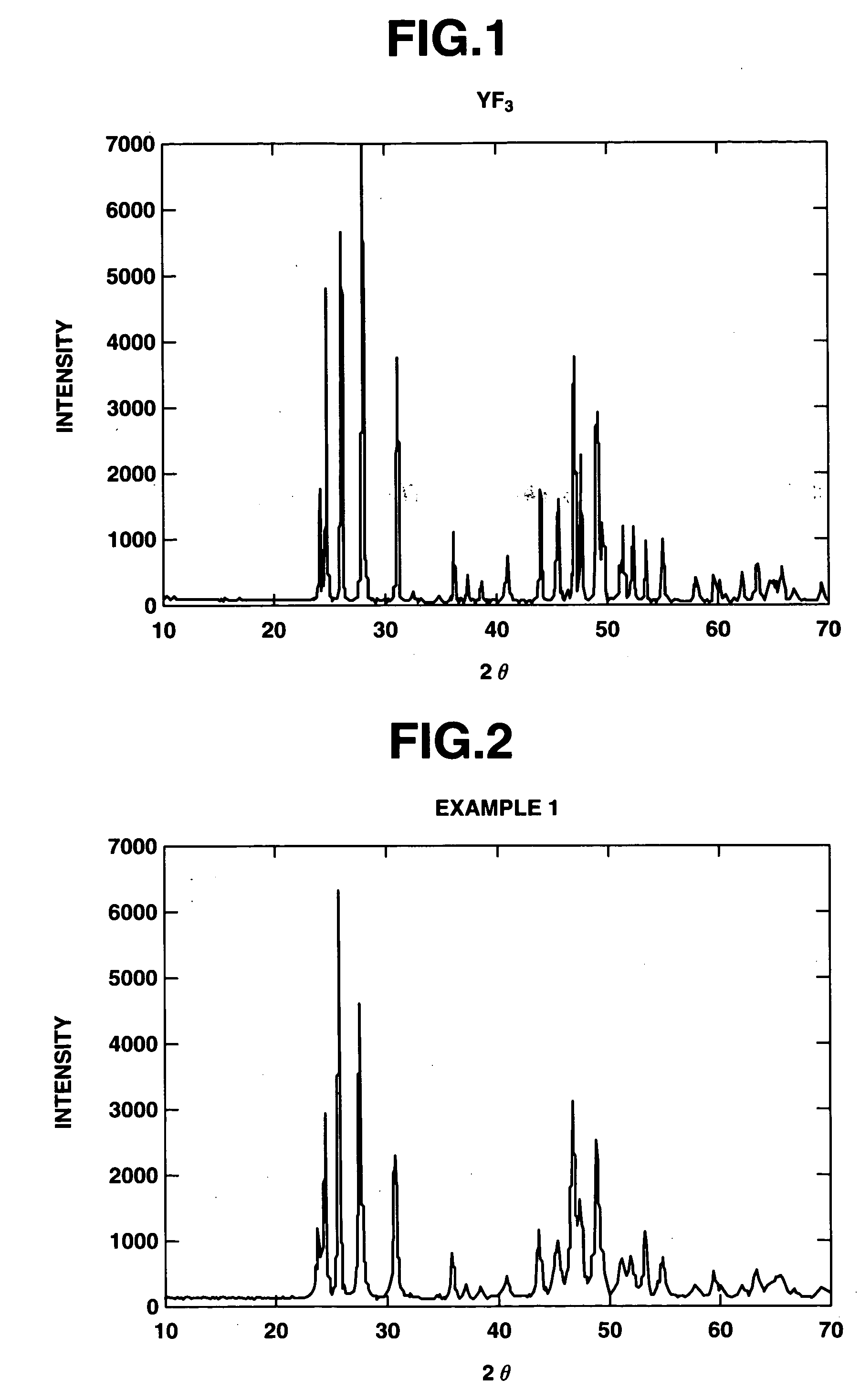
[0106] There was furnished an aluminum alloy substrate of 20 mm square. The surface was degreased with acetone and roughened with abrasives of corundum. By operating an atmospheric plasma spraying apparatus at an output of 40 kW and a spray distance of 100 mm while feeding argon gas as a plasma-forming gas, crystalline YF.sub.3 powder was sprayed at a rate of 30 .mu.m / pass until a thickness of 300 .mu.m was reached. Prior to the spraying, the substrate was roasted with the plasma gas and thereby heated to 250.degree. C. whereupon deposition was started. FIG. 1 is an x-ray diffraction diagram of the crystalline YF.sub.3 powder used herein. It is evident from FIG. 1 that the feed material is highly crystalline YF.sub.3 of single phase.

[0107] The surface of the coating was analyzed by an x-ray diffractometer, with the results shown in FIG. 2.

[0108] As a result of qualitative analysis, the coating was identified to be a single phase coating of JCPDS Card No. 32-1431, the profile having ...

example 2

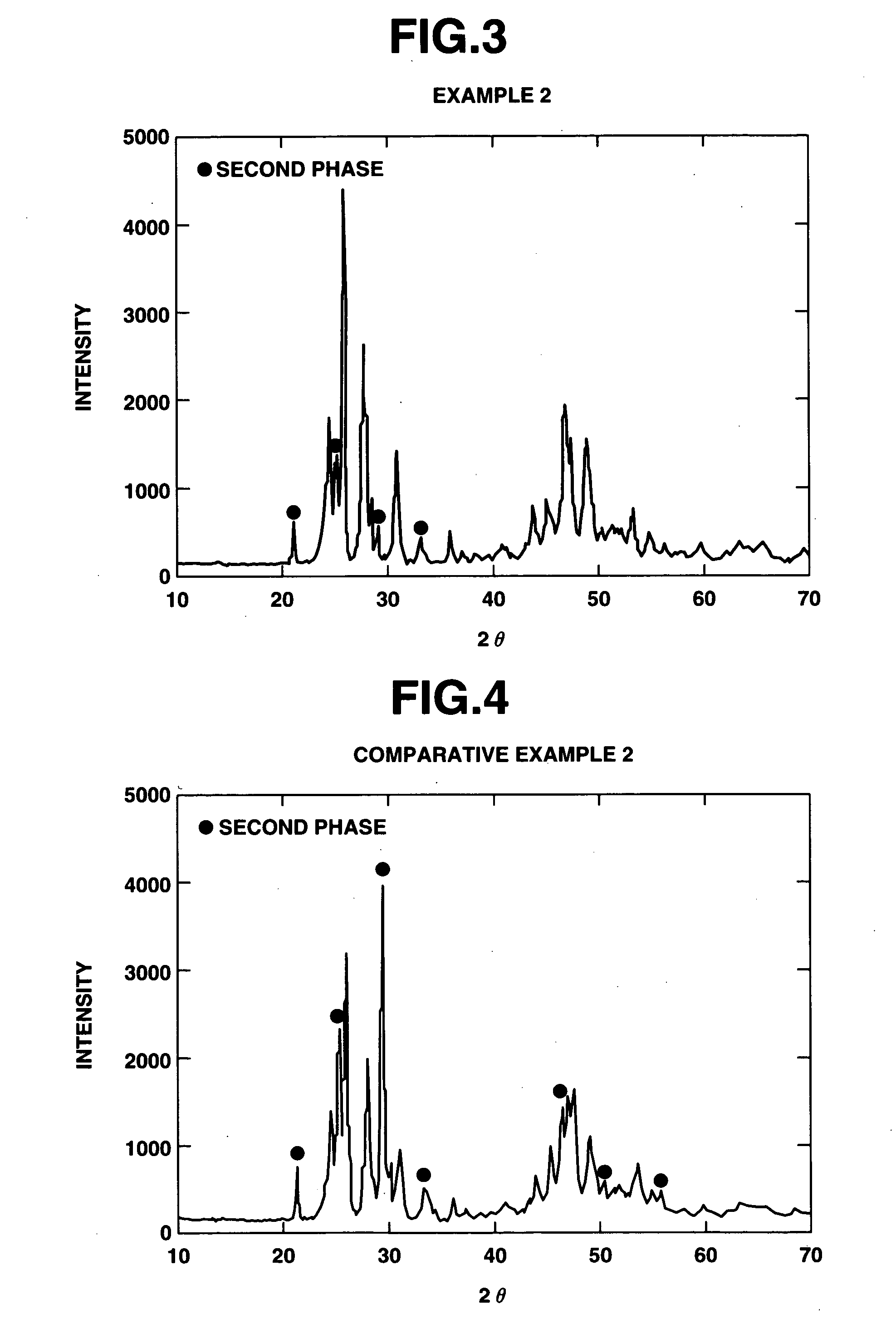
[0112] A coating was deposited under similar conditions to Example 1. Prior to the spraying, the substrate was heated to 80.degree. C. The results of x-ray diffractometry on the coating surface are shown in FIG. 3. The coating contained orthorhombic YF.sub.3 of JCPDS Card No. 32-1431, the diffraction profile of YF.sub.3, and a second phase having peaks at angles 2.theta. of approximately 21.1, 25.2 and 29.3 degrees. The orthorhombic crystal content of this coating was 72% as computed by the above-described procedure.

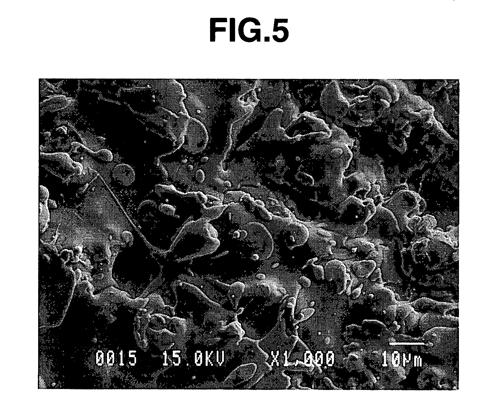
[0113] The surface of the coating was observed under an electron microscope, finding a grain size of 5 .mu.m.

[0114] On this coating, chromaticity measurement and the fluoride plasma resistance test were carried out as in Example 1.

example 3

[0115] As in Example 2, YF.sub.3 was deposited on an aluminum substrate. The resulting coating was heat treated in an air atmosphere at 300.degree. C. for one hour. On this sample, identification of crystalline phase by x-ray diffractometry, quantification, chromaticity measurement and the fluoride plasma resistance test were carried out as in Example 1.


PUM

PropertyMeasurementUnit
Angleaaaaaaaaaa
Fractionaaaaaaaaaa
Fractionaaaaaaaaaa

Abstract

A Group IIIA element fluoride-containing coating comprising a Group IIIA element fluoride phase which contains at least 50% of a crystalline phase of the orthorhombic system belonging to space group Pnma is formed on a member for imparting corrosion resistance so that the member may be used in a corrosive halogen species-containing atmosphere. When the state of a crystalline phase is properly controlled, the coating experiences only a little color change by corrosion. A Group IIIA element fluoride-containing coating having a micro-Vickers hardness Hv of at least 100 is minimized in weight loss by-corrosion.

Description

[0001] 1. Field of the Invention[0002] This invention relates to Group IIIA element fluoride-containing coatings for use in improving the corrosion resistance of members to be exposed to a corrosive halogen species-containing atmosphere, and coated members having such coatings.[0003] 2. Background Art[0004] The applications where corrosive halogen species are present include plasma-assisted processes (e.g., plasma etching and plasma CVD) for semiconductor manufacture, incinerators and the like. In the semiconductor process, objects are etched, cleaned or otherwise treated utilizing the activity of corrosive halogen species. At the same time, members used in the atmosphere where such active halogen species are present are also affected thereby, undergoing corrosion. To minimize such impacts, highly corrosion resistant materials are under study. The members used in the corrosive atmosphere include ceramic materials such as sintered alumina, sintered magnesia, sintered aluminum nitride...

Claims


Application Information

Patent Timeline
IPC IPC(8): C23C14/06C23C16/30C23C30/00C23F11/18
CPCC23C30/00C23C24/04C23C4/04C23C30/005Y10T428/31678C23F11/18
Inventor MAEDA, TAKAONAKANO, HAJIMESHIMA, SATOSHI
Owner SHIN ETSU CHEM IND CO LTD
Why Eureka
Try Eureka