
Protective coating method for pieces made of heat resistant alloys

a technology of alloys and protective coatings, applied in the field of metalurgical and mechanical engineering, can solve the problems of blades operating under very severe conditions, blades may have internal passages, and deterioration, and achieve the effects of improving the durability of parts, improving the set of performance characteristics, and improving the durability of machine parts

Inactive Publication Date: 2007-06-12
PADEROV ANATOLY NIKOLAEVICH +1
View PDF24 Cites 31 Cited by
  • Summary
  • Abstract
  • Description
  • Claims
  • Application Information

AI Technical Summary

Benefits of technology

"The present invention provides a technique for coating deposition on iron-nickel-cobalt-based superalloy surfaces. The coating is made up of multiple layers, including microlayers with different properties and thicknesses. The microlayers are deposited simultaneously or consecutive with ion implantation, using surface impregnation technologies and controlled atmospheres. The technique improves durability of machine parts, especially gas turbine blades and vanes, by providing better protection and preventing oxidation and gas corrosion. The many-layer coating consists of layers with different functions, such as high heat-resisting, high plasticity, barrier, and corrosion-resisting layers. The method can be used in combination with other surface preparation techniques, such as ion implantation, vacuum-plasma, electron beam, and annealing in controlled atmospheres."

Problems solved by technology

Many machine parts have to operate under heavy working load and variable temperature in aggressive environment, which results in their deterioration and calls for protective coating to be applied on such parts.
Such blades operate under very severe conditions: at elevated temperatures, under considerable fatigue and thermal loads, and in aggressive gas flows containing oxygen, sulfur, vanadium oxides and other chemically-active elements.
Some blades may have internal passages, which are prone to oxidization, especially if made of currently employed high temperature superalloys with low content of chromium.
As a result, durability of blade decreases and such blades have to be laid off.
Turbine blades are manufactured of expensive superalloys by employing a complicated technology, for instance, oriented crystallization or monocrystal casting, so their price is extremely high.
Diffusion methods for powder and gas vapor deposition are known to create aluminum intermetallic coatings, which, while having quite high heat-resistance, at the same time possess low resistance to thermal stresses and to corrosion in the chemically aggressive environment of combustion materials.
Coatings alloyed with noble metals are expensive and their use is not always economically sound.
Slip powder technologies can not provide coatings, which would be uniform in thickness, and the density of such coatings is not sufficient.
Aluminide coatings, too, have high thermal conductivity and insufficient correlation between linear expansion coefficients in oxide ceramics layers.
Frequently occurring fault with multi-layer coatings of Me—Cr—Al—Y and their modifications is that they do not provide long enough service life of a machine component either due to insufficient heat-resistance or as a result of flaking and corrosion of the coating during use.
This patent neither fully uses all means to offer maximum resistance to gas corrosion, nor provides protection for internal passages of cooled cavities.
This patent does not cover the issues of coating formation nor does it address the capabilities of patented device to improve the coating technology.

Method used


Image

  • Protective coating method for pieces made of heat resistant alloys
  • Protective coating method for pieces made of heat resistant alloys
  • Protective coating method for pieces made of heat resistant alloys

Examples


Embodiment Construction

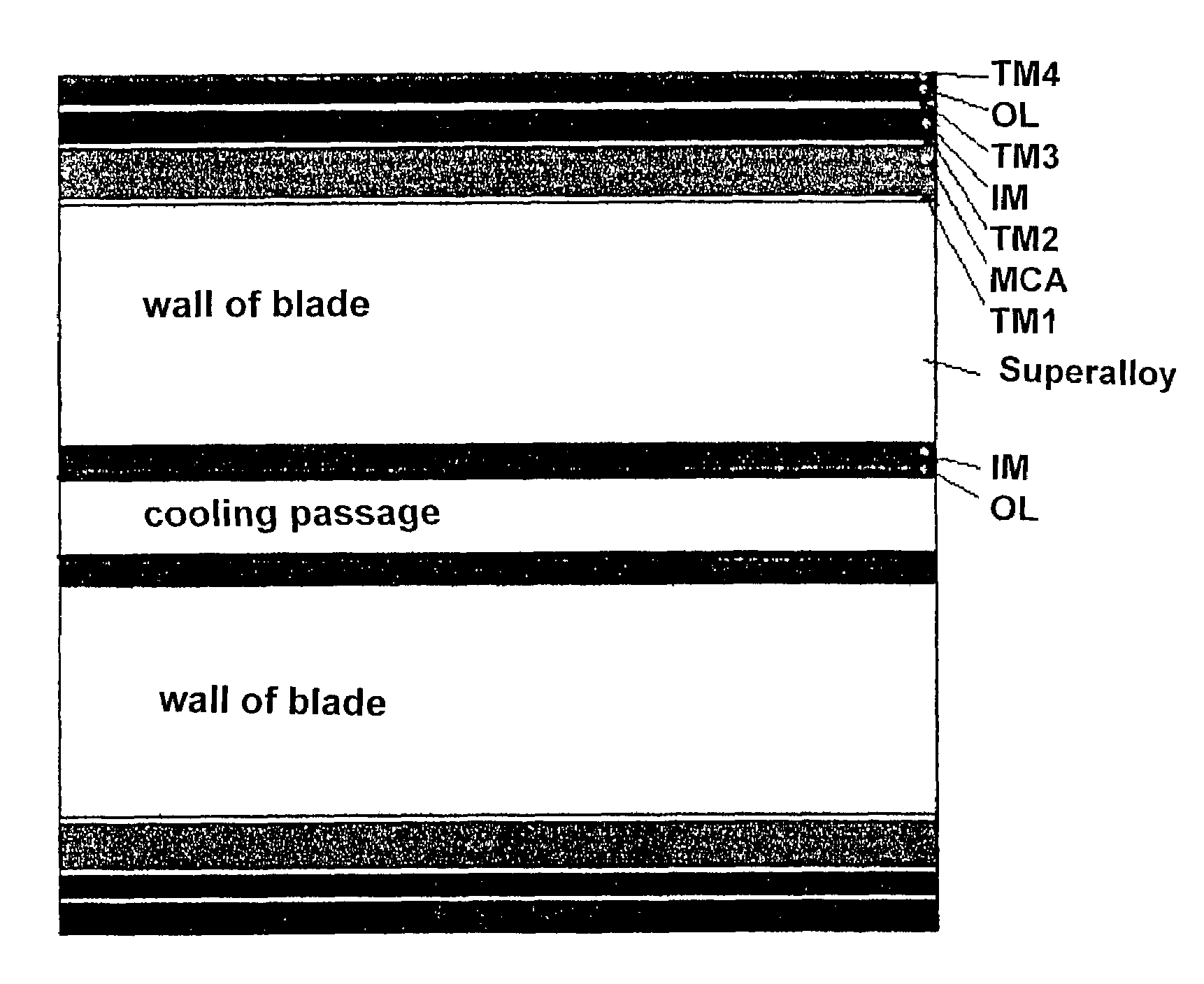
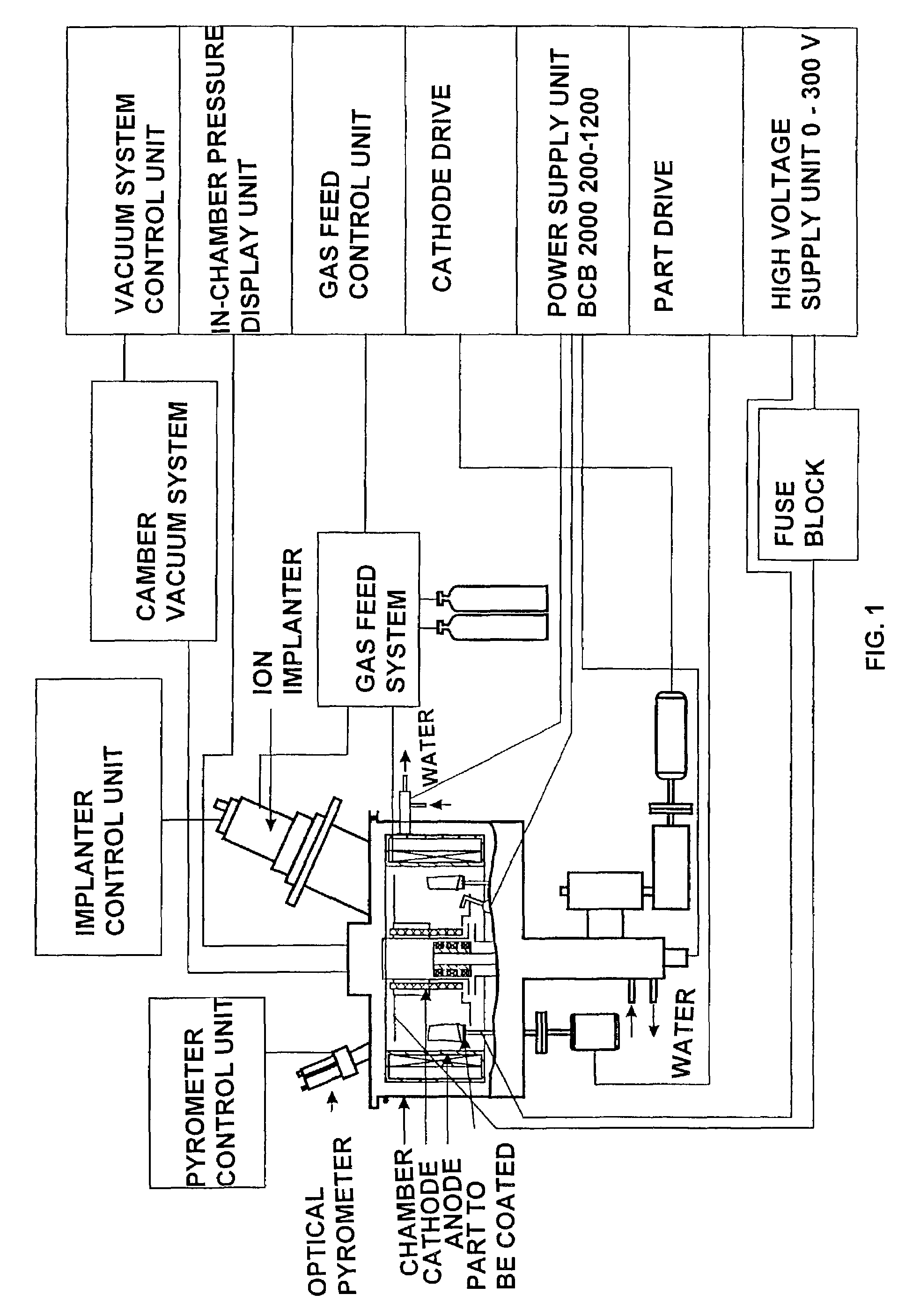
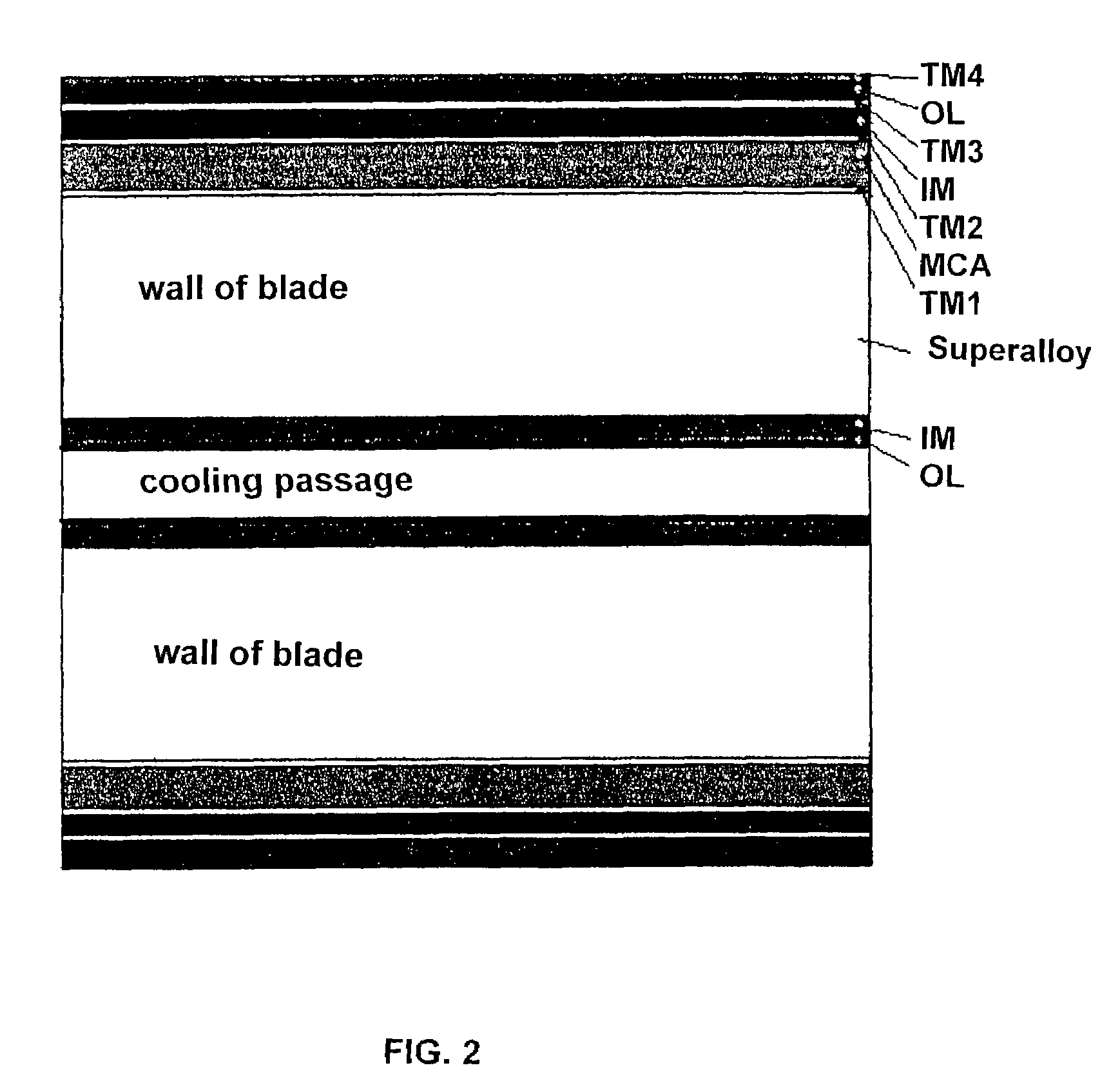
[0033]FIG. 1 / 2 shows a schematic of the ion plasma deposition machine combined with ion implanting facility.

[0034]The machine contains an ion plasma deposition chamber with a rotating table on which the part to be coated is mounted, an inert / non-inert gas feed system monitored to feed the gas atmosphere into the ion plasma deposition chamber, a monitoring system of ion sputtering and coating deposition, and a temperature monitoring device.

[0035]An ion source is mounted in the lid of the working chamber, which produces ions of inert and reacting gases (such as nitrogen, acetylene, methane, diborane, and oxygen) for corresponding implantation by ions of an inert gas (argon, neon). To achieve this, the source is equipped with a self-contained feed monitoring system of gas mixture supply. Besides, the implanter has a source of metal ions. The implanter is mounted in the lid in such a way that the flow of high-energy ions be directed onto the surface of part to be coated, with the part b...


PUM

PropertyMeasurementUnit
thicknessaaaaaaaaaa
thicknessaaaaaaaaaa
accelerating voltageaaaaaaaaaa

Abstract

The invention relates to metallurgy and mechanical engineering, in particular to the development of methods for providing metallic pieces with protective coatings with a view to improving the performance characteristics thereof. In accordance with the inventive method, a multilayer coating is formed by combining and simultaneously or consecutively using of various technologies including ion-plasma evaporation diffusive metallization and controlled atmosphere thermal treatment. The obtained coatings possess superior characteristics with respect to overall properties and are used for gas turbine construction, in particular, for manufacturing gas turbine vanes of aircraft engines.

Description

FIELD OF THE INVENTION[0001]This invention relates to metallurgy and mechanical engineering fields and more specifically to the development of methods that improve service life and durability of machine parts, particularly of turbine components for power production and transport industry, and primarily of aircraft engine gas turbine blades and vanes, by means of modification in protective coating technology.BACKGROUND TO THE INVENTION[0002]Many machine parts have to operate under heavy working load and variable temperature in aggressive environment, which results in their deterioration and calls for protective coating to be applied on such parts. In the field of transport industry and power turbine construction and, particularly, gas turbine manufacturing the surface protection of parts is the most critical. Gas turbine units (GTU) are applied widely in the state-of-the-art technology: aircraft and helicopter's engines, marine gas turbine engines (GTE), power GTU and gas compressor ...

Claims


Application Information

Patent Timeline
Patent Type & Authority Patents(United States)
IPC IPC(8): H05H1/24C23C14/08C23C14/16C23C14/18C23C14/30C23C14/48C23C14/58C23C14/34H05H1/46
CPCC23C14/022C23C14/16C23C14/48C23C14/5806C23C14/5833Y02T50/67Y02T50/60
Inventor PADEROV, ANATOLY NIKOLAEVICHVEXLER, JURY GENRIKHOVICH
Owner PADEROV ANATOLY NIKOLAEVICH
Learn More