Method for bacterial lysis

Inactive Publication Date: 2010-08-12
BOSTON MEDICAL CENTER INC
View PDF4 Cites 54 Cited by
  • Summary
  • Abstract
  • Description
  • Claims
  • Application Information

AI Technical Summary

Benefits of technology

[0042]The proposed microfluidic cell lysis method will have advantages over the existing technologies in that a chip-based sample preparation system will shrink the conventional “bench-top”“macroscale” procedure into a miniature, portable device. The cell lysis chips of the present invention also significantly reduce the need of reagents, and also minimize sample consumption. Such chips also minimize exposure of the practitioner to possible pathogenic microorganisms in a biological sample as well as potential harmful biomolecules released from the lysed cells, for example toxins and nucleic acids released from, for example bacterial cells and other pathoge

Problems solved by technology
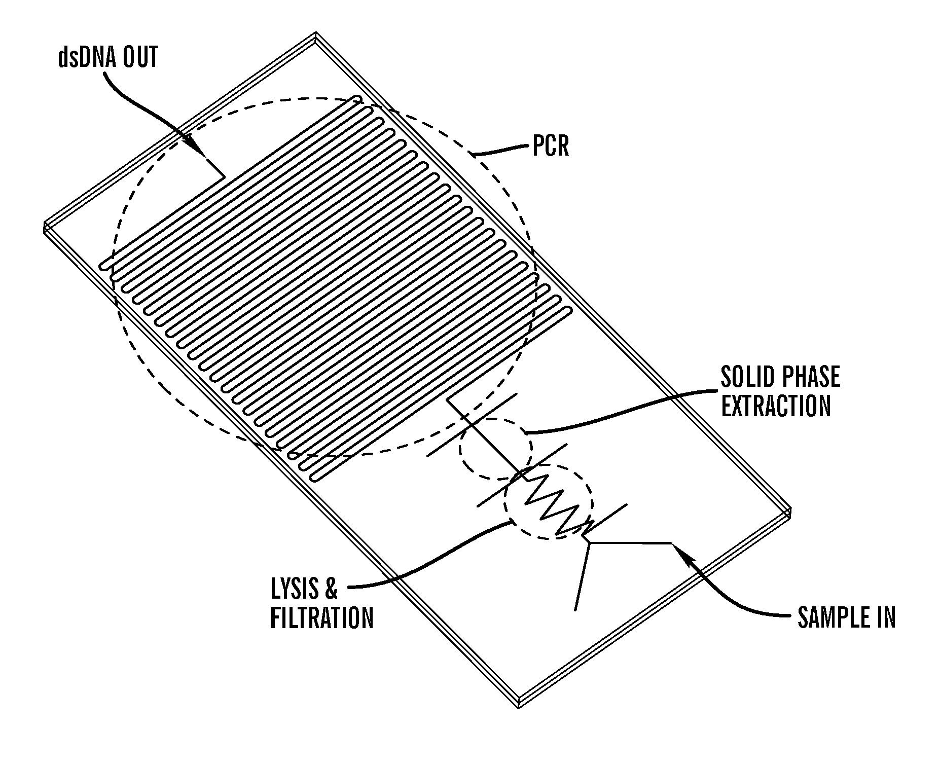
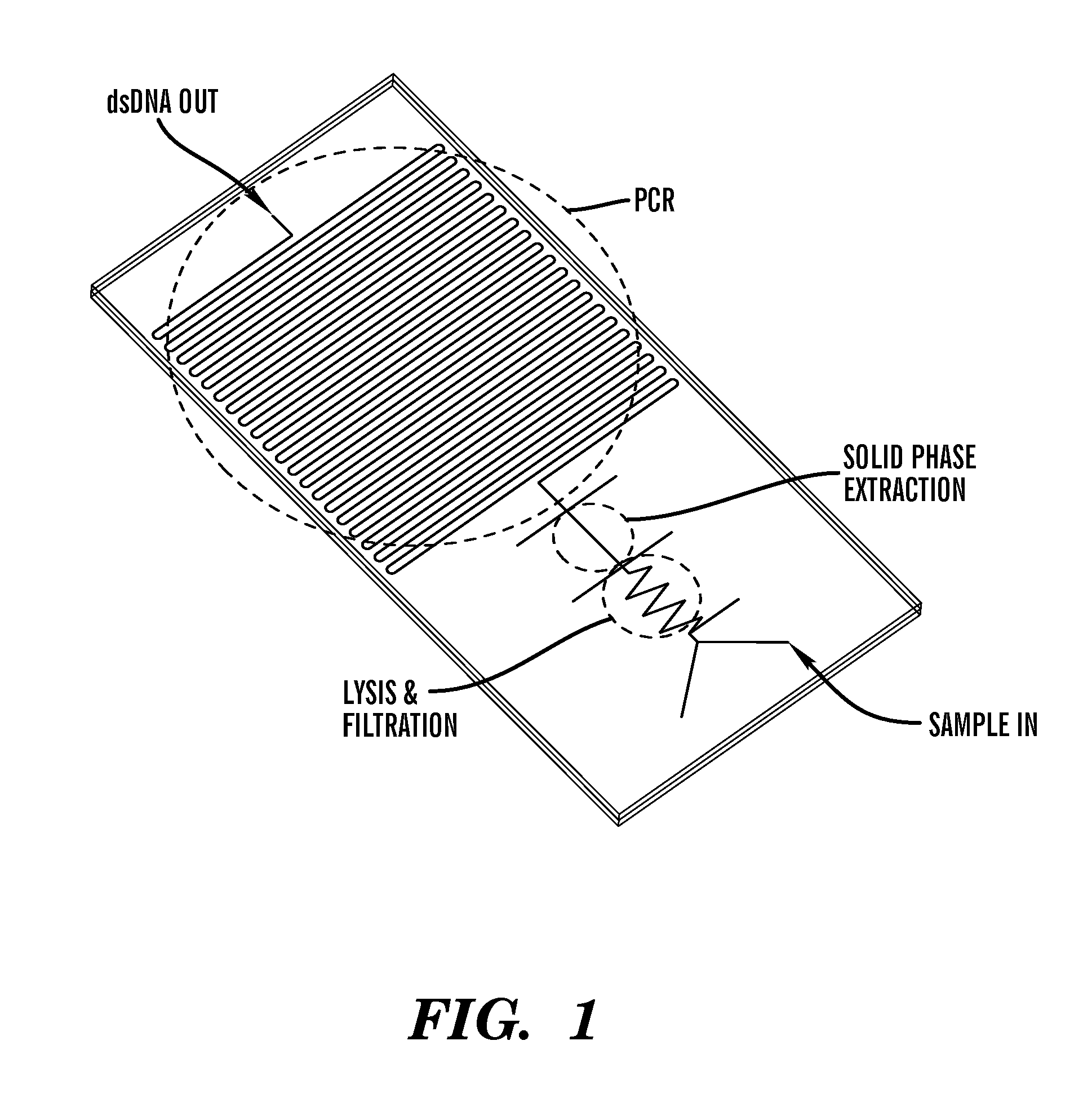
Additionally, the size of Lab-on-Chip devices frequently result in superior assay processing speed due to the shorter travel lengths, lower thermal masses and smaller fluid volumes involved.
Silicon and glass fabrication can be very expensive, while PDMS lacks dimensional stability and has limited shelf-life.
These limitations necessitate the use of alternative materials to make disposable, point-of-care devices, for example, for diagnostic applications.
However, this device is not suitable for lysis of the cells, in particular lysis of bacteria cells.
These methods are very expensive.
However, the sol-gel chemistry involves high temperatures and is not suitable for in situ applications of the polymeric devices.
While mammalian cells can be lysed by a combination of lysis buffer and simple mixing, lysis of bacteria cells takes significantly more effort due to the nature of the cell wall.
Such methods are difficult to implement in other than full diagnostic laboratory settings.
This prevents them from being used for, example critical bacterial strain detection when analyzing causative agents for infections, or when the sample is in limited supply.
Further, the conventional methods of cell lysis, for example bacterial lysis require many labor intensive biological procedures that are typically conducted in a serial fashion using numerous different pieces of equipment and/or solutions.
Such lysis methods have multiple limitations, for example chemicals as a means to lyse bacteria is not desirable for several reasons: Firstly, lysis buffers and enzymes can drive device cost, and thus their use should be minimized.
This makes for either additional logistical difficulty for the device user or additional device complexity, needing to add a chemical mixing module to the overall system.
Finally, overuse of chemicals can complicate downstream processing by interfering with extraction, polymerase chain reaction or electrophoresis.
Other methods that involve mechanical means also have their limitations, for example additional design complexity and need for additional, more complex fabrication methods than are needed for most passive devices.
The addition of potentially costly transducers and electrical interconnects to an otherwise very simple design may compromise the desire to have a device that is affordable to fabricate and is single use disposable.
Compounding the issue is the need for external power supplies, heater elements or ultrasonic transducers, which would be burdensome and undermine the device use as a true point-of-care diagnostic instrument.
Current passive lysis methods used on lab-on-a-chip devices have multiple limitations.
In general, the extensive use of chemicals as a means to lyse bacteria is not desirable for several reasons.
This makes for either additional logistical difficulty for the device user or additional device complexity, needing to add a chemical mixing module to the overall system.
Finally, overuse of chemicals can complicate downstream processing by interfering with extraction, polymerase chain reaction or electrophoresis.
Current mechanical forces to drive cell lysis on lab-on-a-chip devices also have multiple limitations.
However, Lee et al., do not demonstrate the device was effective in lysing bacterial cells.
Furthermore, the construction method utilized to make the nanobarbs in silicon is not transferable to polymer based constructions due to limitations in the replica molding process used to create features.
Current active lysis methods used

Method used


Image

  • Method for bacterial lysis
  • Method for bacterial lysis
  • Method for bacterial lysis

Examples


Example

Example 1

Surface Treatment of Carbon Nanotubes Prior to Embedding in Monolith

[0343]Multi-Walled Carbon Nanotubes within Porous Polymer Monoliths. After assessing and testing a variety of pre-polymer systems for use in the device, the inventors discovered that a pre-polymer system comprising the non-polar solvents, (cyclohexanol / dodecanol) for use with the non-polar monomer (BUMA) was selected. The polar solvents selected, (ethanol / methanol), were selected based upon their miscibility with the polar monomer, (GMA), and results reported in the literature42. The confidence in this pairing was high due to demonstrated successes within the laboratory41.

[0344]In some instances the inventors sometimes added additional constituent parts are added to the pre-polymer for functionality, such as 2-acrylamido-2-methyl-1-propane sulfonic acid, which is frequently used as an electro-osmotic flow promoter, (EOF). Details on each of the pre-polymer formulations that can be used are disclosed in the ...

Example

Example 2

Generation of Polymers Containing Carbon Nanotubes

[0349]The inventors determined the concentrations of nanotubes to use as part of the overall pre-polymer system. The inventor assessed the concentrations of BUMA based pre-polymer solutions with nanotube concentrations from 0.001M to 0.5M that resulted in success fabrication. The inventors discovered that at the higher concentrations the repeatability began to suffer and after reviewing scanning electron micrographs a concentration of 0.25M was selected for repeated fabrication purposes.

[0350]In the case of the GMA based pre-polymer system the stock solution purchased from Nanolabs was initially used, (0.0033M in ethanol), providing a much lower concentration than that used in the BUMA system. After discovering a higher success with the lower concentrations, the inventors used suspension that were concentrated ten-fold and a larger concentration, (but still much lower concentration than used in the BUMA system) to fabricate ...

Example

Example 3

Grafting Channels for Adherence of Carbon Nanotube Impregnated Porous Polymer

[0353]Processing of the Carbon Nanotube Impregnated Porous Polymer Monolith

[0354]Once a pre-polymer solution was prepared and a polymeric microfluidic chip was fabricated the pre-polymer solution was pipetted into the channels and in-situ polymerization can be used to create the porous polymer monolith. Before this can happen, the inventors added an additional grafting layer to the inside of the channels. Since Zeonex is a Teflon-like material, it exhibits extremely low surface energy making it difficult to get the porous polymer monolith to bind to the channel wall. In order to solve this problem, the inventors used a “grafting mix” comprising a pre-polymer solution, comprising of a 1:1 mixture of Ethlyene diacrylate, (EDA) and Methyl methacrylate, (MMA), combined with enzophenone (an photo-sensitizer), and introduced to the channels following a thorough methanol wash (demonstrated by Bhattacharry...


PUM

PropertyMeasurementUnit
Lengthaaaaaaaaaa
Lengthaaaaaaaaaa
Diameteraaaaaaaaaa

Abstract

The present invention is directed to a microfluidic device for lysis of cells, such as bacteria and microorganisms. In particular, the present invention relates to microfluidic devices and methods of manufacture of such microfluidic devices comprising a substrate with at least one channel packed with a polymer monolith embedded with carbon particles, for example carbon nanotubes. The microfluidic devices and methods of the present invention are useful for cell lysis of cells within a biological sample, such as a untreated biological sample comprising microorganisms, such as but not limited to gram positive and gram negative bacteria. In some embodiments, the microfluidic devices of the present invention can also optionally comprise other modules enabling further processing of the biological sample, for example isolation, purification and detection of biomolecules released from the lysed cells, such as but not limited to nucleic acids or proteins or peptides from the lysed cells, providing a complete Lab-on-a-Chip analysis system for biomolecules released from difficult to lyse microorganisms in a single step or process. The microfluidic devices of the present invention can also be adapted and are useful to methods to enrich for microorganisms in a biological sample, for example enrich for a desired type of bacteria within a biological sample. The microfluidic devices and methods of the present invention can be adapted to perform highly efficient lysis of microorganisms within a biological sample for diagnostic tests, for example for diagnosis of infectious agents and pathogens, such as bacteria, viruses or parasites.

Description

CROSS REFERENCED APPLICATIONS[0001]This application claims benefit under 35 U.S.C. 119(e) of U.S. Provisional Patent Application Ser. No. 60 / 921,404 filed on Apr. 2, 2007, and U.S. Provisional Patent Application 60 / 925,445 filed on Apr. 20, 2007, the contents of each are incorporated herein in their entity by reference.FIELD OF THE INVENTION[0002]The present invention relates generally to bacterial lysis, and more particularly to methods for bacterial lysis using a microfluidic device. The present invention relates to a device and methods for their manufacture as well as isolation, purification and detection of biological molecules, such as nucleic acids and proteins. Specifically, the invention relates to the preparation of microfluidic device comprising a polymer embedded with carbon particles and methods for cell lysis using such microfluidic device. In particular, the methods relates to the lysis of bacteria using a microfluidic device. The device can also optionally comprise mo...

Claims


Application Information

Patent Timeline
IPC IPC(8): C12Q1/68C12M1/34
CPCB01L3/502707B01L2200/10B01L2300/0681B82Y30/00B82Y40/00C01B31/0206C01B2202/34C12Q1/6806C12N1/066C01B2202/36C12Q2565/629C12Q2531/113C01B32/15
Inventor KLAPPERICH, CATHERINE M.KAUFMAN, JESSICA DAREKULINSKI, MARIA DOMINIKAALTMAN, DAVIDSINGH, SATISH
Owner BOSTON MEDICAL CENTER INC
Why Eureka
Try Eureka