Resin structure

a technology of resin structure and resin cylinder, which is applied in the field of resin structure, can solve the problems of unsatisfactory barrier properties of gasoline and other specific oils, difficult to directly use them for fuel tanks and oil tanks for automobiles, and difficult to achieve the effect of enhancing the productivity and industrial application of invention, good gas barrier properties, and convenient us

Inactive Publication Date: 2005-05-31
MITSUI CHEM INC +1
View PDF11 Cites 13 Cited by
  • Summary
  • Abstract
  • Description
  • Claims
  • Application Information

AI Technical Summary

Benefits of technology

[0097]The method for producing the resin structure of the invention is not specifically defined, so far as the resin structure produced can have the morphology that satisfies the requirement of the invention. For realizing the preferred morphology, for example, the polyolefin resin and the PPS resin to form the resin structure are fed into separate two extruders through the respective main feeders and an inorganic filler is added thereto through a side feeder disposed at the top of each extruder; or the polyolefin resin and the PPS resin are first kneaded in melt, and an inorganic filler is added to the mixed resin melt.
[0098]The thermoplastic resin structure and the multi-layer structure of the invention may be shaped in any known manner, and the method of molding them is not specifically defined, for which, for example, employable is injection molding, extrusion molding, blow molding or press molding. Especially preferred for molding them is at least one method selected from injection molding, injection compression molding and compression molding for enhancing the productivity and the industrial application of the invention. The molding temperature may fall generally within a range higher than the melting point of the PPS resin by from 5 to 50° C. In general, the moldings are single-layered, but may be multi-layered in a two-layer molding method.
[0099]The layer configuration in the multi-layer structure of the invention is not specifically defined. All the layers of the multi-layer structure may be formed of the thermoplastic resin structure of the invention, or any other thermoplastic resin may be used for some layers. In two-layered multi-layer structures, the layer of the thermoplastic resin structure of the invention is preferably the innermost layer in order that it can fully exhibit its transmission-resistant effect. The moldings obtained herein may be integrated together or with other moldings by the use of an adhesive or through hot-sealing, and the method of integrating them is not specifically defined, for which are employable any known techniques.
[0100]As the thermoplastic resin structure and the multi-layer structure of the invention have good gas barrier properties, and are durable and easy to work, they are favorable for containers for transportation and / or storage of liquid chemicals and gases, for the attached parts of such containers, and also for multi-layered tubes or multi-layered blow moldings to be formed through coextrusion. Regarding the liquid chemicals and the gases, the resin structure and the multi-layer structure are highly resistant to transmission therethrough of vapors and / or liquids and also evaporated gases, for example, Flon-11, Flon-12, Flon-21, Flon-22, Flon-113, Flon-114, Flon-115, Flon-134a, Flon-32, Flon-123, Flon-124, Flon-125, Flon-143a, Flon-141b, Flon-142b, Flon-225, Flon-C318, R-502, 1,1,1-trichloroethane, methyl chloride, methylene chloride, ethyl chloride, methylchloroform, propane, isobutane, n-butane, dimethyl ether, castor oil-based brake fluid, glycol ether-based brake fluid, borate-based brake fluid, brake fluid for use in extremely cold regions, silicone oil-based brake fluid, mineral oil-based brake fluid, power steering oil, windshield wash, gasoline, methanol, ethanol, isobutanol, butanol, nitrogen, oxygen, hydrogen, carbon dioxide, methane, propane, natural gas, argon, helium, xenon and medicines. Therefore, the resin structure and the multi-layer structure have many applications for parts of electric and electronic appliances, medical appliances, food-related appliances, household and office-use appliances, constructions-related parts, furniture parts and others. For example, their applications are for films of transmission resistance against vapors and / or liquids mentioned above; as well as for tanks and bottles for automobile parts, parts for medical appliances and daily commodities, such as air bags, bottles for liquid chemicals such as shampoo, rinse, liquid soap, detergent, tanks for storage of liquid chemicals, tanks for storage of gases, coolant tanks, oil transportation tanks, disinfectant tanks, tanks for blood transfusion pumps, fuel tanks, windshield wash tanks, oil reservoir tanks, canisters; Attached parts for such tanks and bottles, such as valves, e.g., cutoff valves, joints, gauges for attendant pumps, cases and other parts, various fuel tubes and connecting parts (e.g., connectors), e.g., fuel filler under-pipes, ORVR hoses, reserve hoses, bent hoses, oil tubes and connecting parts, brake hoses and connecting parts, windshield wash nozzles and hoses, cooler hoses and connecting parts for cooling water and coolant, tubes and connecting parts for coolant for air conditioners, floor-warming pipes and connecting parts, fire extinguishers and fire hoses, tubes, connecting parts and valves for medical cooling devices, tubes for transportation of liquid chemicals and gases, containers for storage of liquid chemicals, and other applications requiring liquid chemical and vapor transmission resistance; and machine parts such as automobile parts, internal combustion engine parts, and housings for electric tools.
[0101]The invention is described in detail hereinunder with reference to Examples. However, the scope of the invention is not limited to only the following Examples.
[0102]Using a 40 mmφ extruder with a tubular die, a sizing die to cool the tube extruded out of the extruder and to control the size of the tube and a take-up unit disposed at its top, a tube having an outer diameter of 8 mm and an inner diameter of 6 mm was molded. The tube was cut into a length of 20 cm. One end of the sample was sealed up, just 6 g of an alcohol gasoline mixture of commercially-available regular gasoline / ethanol of 75 / 25 by weight was put into it, and the other end thereof was sealed up. With that, the overall weight of the sample was measured. The sample was put into an explosion-proof oven at 60° C., and kept therein for 500 hours, and its weight loss was measured.

Problems solved by technology
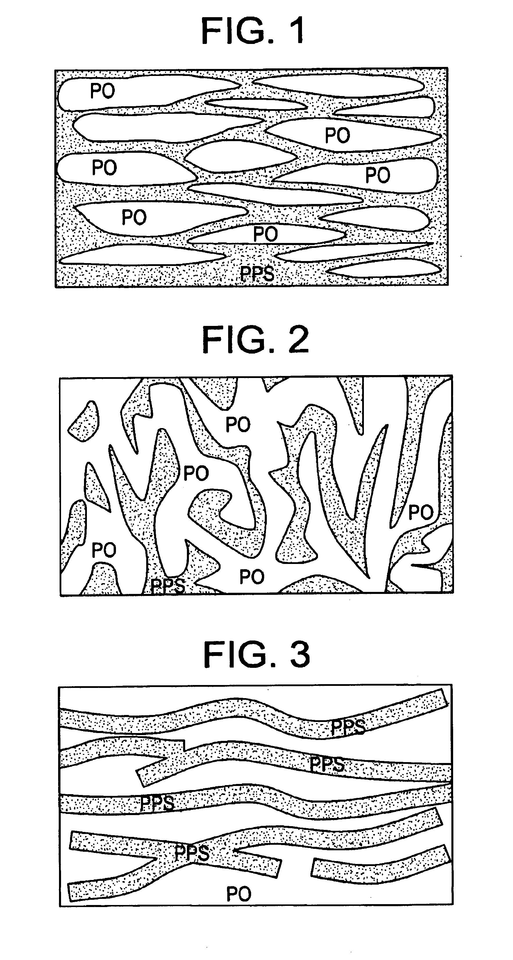
However, since polyolefin resins are poorly resistant to liquid chemical and vapor transmission through them, their use is often limited, and it is desired to improve them.
The method could improve the transmission resistance of the resin compositions and moldings over that of moldings of polyolefin resin alone, but is still unsatisfactory.
Polyethylene, polypropylene and other polyolefin containers are the most popular plastic containers, but their barrier properties against gasoline and other specific oils are unsatisfactory.
Therefore, it is difficult to directly use them for fuel tanks and oil tanks for automobiles.
However, the recent tendency in the field of automobile fuel is being toward using a mixture of gasoline and alcohol, gasohol, for which the plastic containers obtainable in the above-mentioned prior art are unsatisfactory in point of their barrier properties.
However, since its interlayer adhesiveness to other resin is poor, PPS resin has some problems in that its coextrusion and lamination with other resin materials such as polyethylene, polypropylene and other polyolefins is difficult and its main component must be an expensive specific PPS resin.
For these reasons, the application range of PPS resin is limited.

Method used


Image

  • Resin structure
  • Resin structure
  • Resin structure

Examples


reference example 1

Preparation of PPS Copolymer

[0108]3.26 kg of sodium sulfide (25 mols, containing 40% crystal water), 4 g of sodium hydroxide, 1.36 kg of sodium acetate trihydrate (about 10 mols), and 7.9 kg of N-methylpyrrolidone were fed into an autoclave equipped with a stirrer, and gradually heated up to 205° C. with stirring, and about 1.5 liters of distillate containing 1.36 kg of water was removed. To the residual mixture, added were 3.38 kg of 1,4-dichlorobenzene (23.0 mols), 0.37 kg of 1,3-dichlorobenzene (2.5 mols), and 2 kg of NMP, and heated at 265° C. for 5 hours. The reaction product was washed three times with hot water at 70° C., then with aqueous acetic acid solution with pH=4 at 60° C., and further four times with hot water at 70° C., and then dried under reduced pressure at 80° C. for 24 hours to obtain about 2 kg of a PPS copolymer resin having a melting point of 255° C. and MFR of 800 g / 10 min (at 315° C. under 5000 g).

[0109]The polyolefin resins and PPS used in Examples and Com...

examples 1 to 15

, COMPARATIVE EXAMPLES 1 TO 4

[0111]As in Tables 1 and 2, the mixture previously prepared by melting and kneading the PPS resin and a compatibilizer (ethylene / glycidyl methacrylate copolymer, 90 / 10% by weight), and the polyolefin resin were fed into a double-screw extruder, Nippon Seikosho's TEX 30 Model through its main feeder. The inorganic filler, if used, was fed thereinto through a side feeder provided at some part of the cylinder. These were kneaded in melt in the extruder at 300° C., for which the screw revolution was 200 rpm. The resulting pellets were dried, and then injection-molded into test pieces. The injection-molding machine used was Toshiba Kikai's IS100FA, and the mold temperature was 80° C. In addition, the pellets prepared in the same manner as above were molded into tubes for the test for alcohol gasoline transmission through them. The data of the transmission resistance and the mechanical strength of the samples are given in Tables 1 and 2. Some samples were anal...

examples 16 to 32

, COMPARATIVE EXAMPLES 5 TO 8

[0116]As in Tables 3 to 5, the PPS resin was mixed with a compatibilizer (ethylene / glycidyl methacrylate copolymer, 90 / 10% by weight), the resulting mixture was fed into a double-screw extruder, Nippon Seikosho's TEX 30 Model through its main feeder with the polyolefin resin being thereinto through a side feeder provided at some part of the cylinder, and these were kneaded in melt at 270 to 300° C., for which the screw revolution was 200 rpm. The resulting pellets were dried, and then molded into tubes.

[0117]In that manner, molded were three-resin three-layer tubes composed of one barrier layer (α), one neighboring layer (β) of thermoplastic resin, and one adhesive layer (γ) between the barrier layer and the neighboring layer (or two-resin two-layer tubes not having the adhesive layer). For these, the molding machine used has three extruders, a forming die, a sizing die and a take-up unit, in which the resin melts extruded out of the three extruders are ...


PUM

PropertyMeasurementUnit
densityaaaaaaaaaa
melt flow rateaaaaaaaaaa
degree of crystallinityaaaaaaaaaa

Abstract

Provided is a thermoplastic resin structure formed of a resin composition that comprises substantially (a) from 5 to 80% by volume of a polyolefin resin and (b) from 20 to 95% by volume of a polyphenylene sulfide resin, which is characterized in that, in morphology therein seen through electronicmicroscopy, the polyphenylene sulfide resin (b) forms a matrix phase (continuous phase) and the polyolefin resin (a) forms a disperse phase. The thermoplastic resin structure gives plastic containers, tubes and their Attached parts having good barrier properties, strength, durability and workability.

Description

TECHNICAL FIELD[0001]The present invention relates to resin structures of good vapor and / or liquid transmission resistance, and their use. In particular, the invention relates to resin moldings of specific transmission resistance and workability, which are obtained by forming a specific morphology of polyolefin resin and polyphenylene sulfide resin (hereinafter referred to as PPS resin) and are favorable for vapor and / or liquid barrier articles, to such resin structures favorable for containers and pipes for storage and transportation of liquid chemicals such as oil and gasoline, to those favorable for wrapping and packaging materials and containers for foods and medicines, and to their use.BACKGROUND ART[0002]Polyolefin resins such as polyethylene and polypropylene are the most popular plastics that are widely used for daily necessaries, toys, machine parts, electric and electronic parts, and automobile parts. The recent requirement increasing in the art is for gas-barrier (transmi...

Claims


Application Information

Patent Timeline
Patent Type & Authority Patents(United States)
IPC IPC(8): B32B27/08C08L23/00C08L23/02C08L81/00C08L81/02
CPCB32B27/08C08L23/02C08L81/02C08L81/00Y10T428/139Y10T428/1393Y10T428/1352C08L2666/04Y10T428/31507Y10T428/31757Y10T428/31797Y10T428/31913Y10T428/31917C08J2300/22C08L23/0815B32B27/32B32B2307/7242B32B2307/7265B32B2323/04B32B2323/10B32B2355/02B32B2369/00B32B2377/00B32B2439/00B32B2439/70B32B2439/80B32B2597/00
Inventor MATSUOKA, HIDEOHAMAGUCHI, MITSUSHIGEKOBAYASHI, KAZUHIKOTODO, AKIRAKODA, TAKU
Owner MITSUI CHEM INC
Why Eureka
Try Eureka