
Process for forming coatings on metallic bodies and an apparatus for carrying out the process

a technology of metallic bodies and coatings, applied in the direction of manufacturing tools, electric circuits, electric circuits, etc., can solve the problems of poor resistance to wear and tear, poor and inability to provide a high level of protection against wear and tear and corrosion, so as to save the cost of machining or grinding required to remove the external porous layer

Inactive Publication Date: 2003-05-22
M S INT ADVANCED RES CENT FOR POWDER METALLURGY & NEW METERIALS ARCI
View PDF1 Cites 13 Cited by
  • Summary
  • Abstract
  • Description
  • Claims
  • Application Information

AI Technical Summary

Benefits of technology

[0021] Another object of the present invention is to propose an improved process for micro arc oxidation to protect the surface of reactive metals and their alloys, in particular aluminum and its alloy bodies against wear, corrosion and oxidation.
[0023] Still another object of the present is to provide an improved process for micro arc oxidation for obtaining coatings on the surfaces of reactive metals and their alloys which is simple and economical.
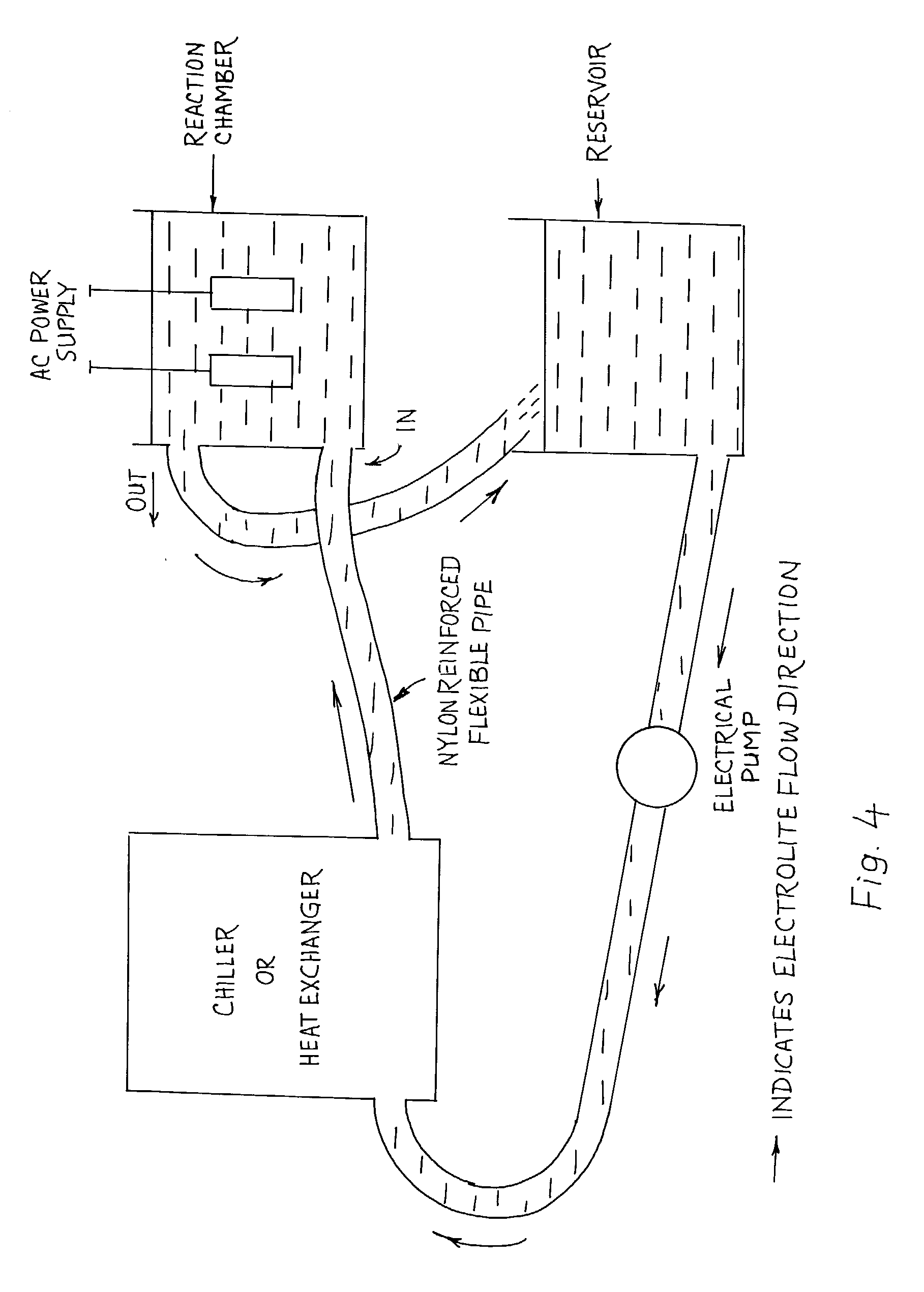
[0025] The objects of the present invention are achieved by providing a process involving electro-thermal and electro-chemical oxidation of reactive metals and their alloys, in particular aluminum and its alloy bodies in a specially prepared alkaline electrolytic solution whose pH is>12 and conductivity>2 milli mhos. Electrolytic solution is prepared by directly adding the additives while the de-ionized / distilled water is in continuous circulation through the reaction chamber. By this method, the time required to uniform mixing of the additives with the water is reduced, as well as the necessity of mechanical stirrer if the electrolyte is externally prepared is also avoided. An electrolyte reservoir and a heat exchanger is connected in series with the reaction chamber facilitate the processing of larger components with a simple alteration in the reaction chamber dimensions thereby avoiding any other design changes.
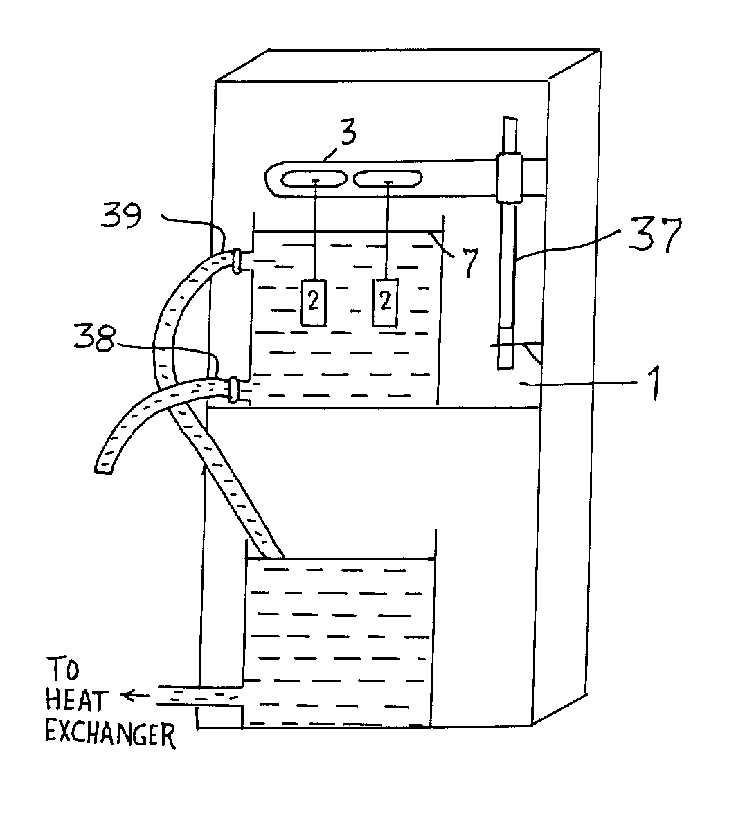
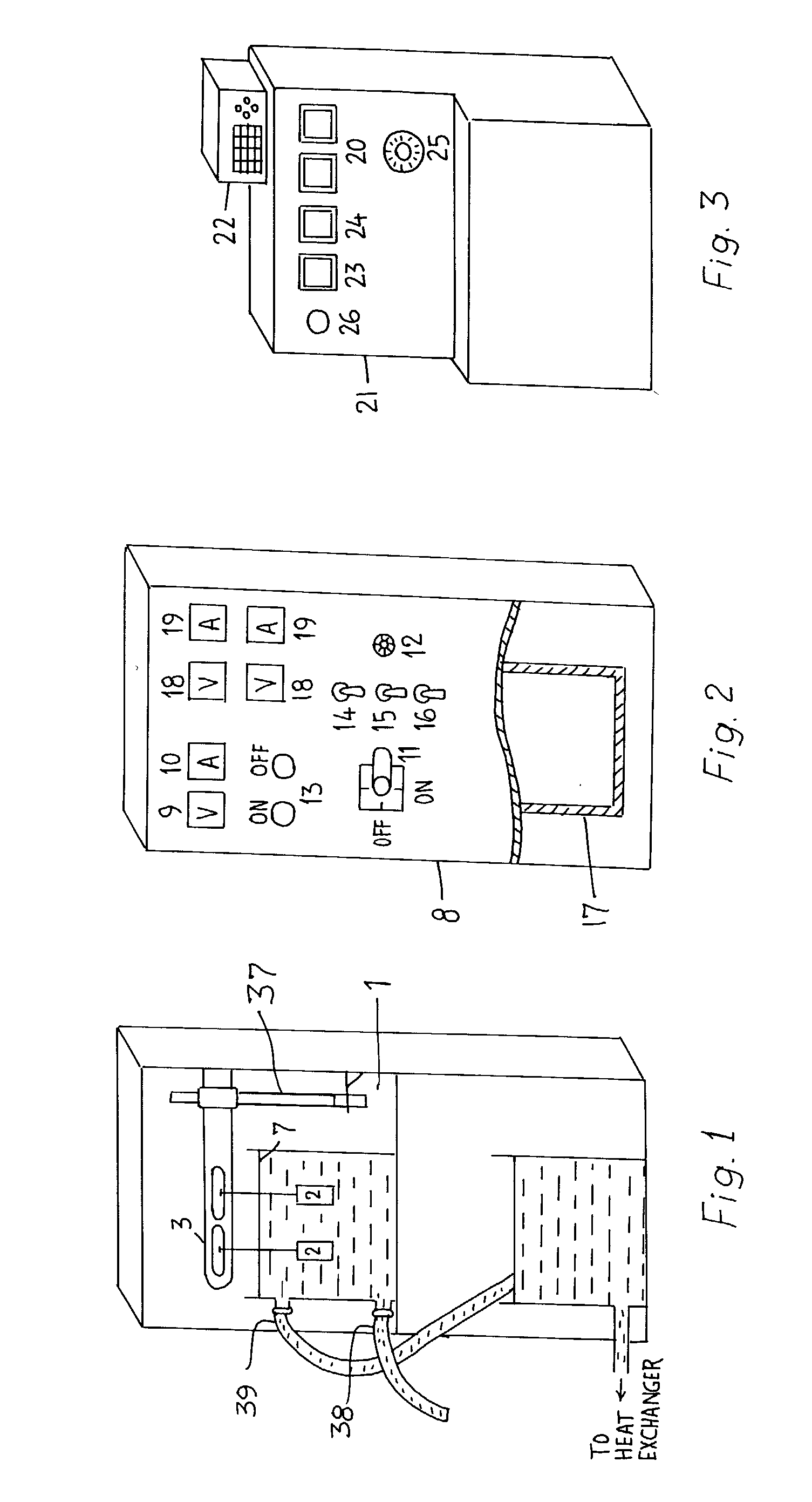
[0032] Accordingly, the present invention provides an improved process for forming ceramic composite coatings on bodies of reactive metals and alloys which comprises electrolysing in a non-metallic, non-reactive, non-conductive reaction chamber (1) containing an alkaline electrolytic solution having a pH>12 and conductivity>2 milli mhos, comprising potassium hydroxide, sodium tetra silicate and de-ionized or distilled water, immersing at least two metallic bodies (2) selected from the reactive group of metals on which coatings have to be effected, the bodies being connected to the electrical power carrying arm (3) in a movable manner, each body being connected to the transformer (17) passing modified wave multiphase alternating current across the said bodies by means of two back-back paralally connected thyristors 4 (FIG. 5) for a period based on the desired thickness of the coatings to be achieved, slowly increasing the current being supplied to the said bodies till the required current density is achieved, then maintaining the current at the same level throughout the process, the elctric potential being further increased gradually to compensate the increasing resistance of the coating when the visible arcing at the surface of the immersed regions of the said bodies is noticed, regulating the composition of the electrolyte by measuring its pH and conductivity during the process by conventional methods, maintaining the temperature of the electrolyte between the range of 4 to 50 degree C. and keeping the electrolyte in continues circulation throughout the process.
[0037] Throughout the process, the electrolyte is kept in a continuous circulation around the bodies under coating by means of an electrical pump. Electrolyte entering the non-metallic, non-conductive, non-reactive chamber at the bottom and leaves from the top avoid any gaseous film / envelope formation at the bottom surfaces of the said bodies. A heat exchanger and / or a chiller may be placed externally in the electrolyte flowing circuit so as to control the temperature of the electrolyte at any point between 4 degree C. and 50 degree C. Continuous electrolyte circulation ensures the homogeneity of the electrolyte and also advantageous for effective heat dissipation from the surface of the bodies. This is very important as it avoids the excessive evaporation of the electrolyte due to intense electrical arcing on the sample surface thereby making the process more eco-friendly, In the electrolyte the ratio between the alkali and metal silicate is maintained constant and the composition is regulated by the pH and conductivity of the electrolytic solution measured form time to time during the process.
[0041] By carrying out the process as described above it is possible to obtain coatings on the surfaces of reactive metals and their alloys particularly on aluminium and its alloys to a predetermined thickness in few minutes. Porosity in the coatings thus obtained is significantly reduced to negligible levels, formation of external porous layer is completely eliminated, dense and uniform coatings are also achieved through the process according to the present invention. The cost of machining or grinding required to remove the external porous layer is saved. The components prepared by this process can be directly subjected to the wear, corrosion resistant applications. Further the coatings produced by this method are very hard, adherent, smooth, dense and uniform than the coatings produced in the prior art.

Problems solved by technology

However, there exists a limitation to use these materials beyond a certain point, the limitation arises from the fact that these materials exhibit poor resistance to wear and tear, chemical attack and heat.
But the resultant coatings are found to be porous, weekly adherent to the substrate, thereby can not provide high level protection against wear and tear and corrosion.
More over, coating deposition rates achieved are also low in the anodizing process.
However, thermal spray techniques demand a high degree of pre coating and post coating operations which are often cost inductive.
Size, shape and complexity in geometry of the engineering components do restrict the applicability of the thermal spray techniques.
Moreover, these techniques demand high quality as well as costly powders such as Alumina, Alumina-Titania, Tungsten Carbide-Cobalt, Chromium Carbide-Nickel Chrome prepared by specially developed manufacturing routes such as sol-gel, atomization, fusing, sintering & crushing, chemical reduction and blending.
Since these coating techniques employ spraying of heated powder particles on to the relatively cold surfaces, often results in poor metallurgical bonding between the substrate and the coating.
These coatings are often characterized by inherent porosity, micro cracks and higher levels of residual stresses which in turn leads to the failure of the coatings in the case of critical applications.
Although the resultant coatings were identified to have strong adherence with the substrate no information is available with respect to the density and uniformity of the coatings achieved.
However, in the process explained above the applicants did not maintain any particular ratio between the alkali and metal silicate.
Too high silicate concentration in the electrolyte causes higher coating built up especially at the sample edges rather than at the other portions of the sample thus resulting in a non-uniform coating.
Apart from the fact that these machining or grinding operations are costly, machining / grinding of coated parts of complex, non-symmetric shapes is extremely difficult and demands high degree of automated machinery and higher skill levels also.
This effictively increases the cost of the coating per unit volume.
The prior art processes of micro anrc oxidation processes through yielded thick, adherent coatings with higher coating deposition rates but failed to produce dense and uniform layers which are essentially required to impart high hardness, higher wear resistance against abrasion, sliding and erosion wear modes as well as with relatively better surface finish.
Also, coatings with higher fraction of inherent porosity will not give satisfactory corrosion resistance and dielectric properties.
However, there exists a serious drawback with this kind of setup.
This makes the process more cost inductive.

Method used


Image

  • Process for forming coatings on metallic bodies and an apparatus for carrying out the process
  • Process for forming coatings on metallic bodies and an apparatus for carrying out the process
  • Process for forming coatings on metallic bodies and an apparatus for carrying out the process

Examples


example 1

[0046] Two aluminium 7075 alloy specimens of 10.times.15.times.20 mm dimension are connected to the output of the high voltage transformer. The total surface area of each sample is 13 cm.sup.2. The current density selected based on a single sample is 0.3 A / cm.sup.2. Electrolyte containing 4 grams of potassium hydroxide and 2 grams of sodium tetra silicate per liter of de-ionized water. Electrolyte is allowed to circulate through the reaction chamber throughout the process. Electrolyte temperature is maintained between 4-6 degree C. In order to exercise better control over the kinetics of the coating process, current density is maintained constant throughout the experiment. Voltage increased up to a maximum of 450 V by the end of 60 minute test run time. At the end of 1 hour, electrical power was switched off, samples were taken out, cleaned in fresh running water and dried with warm air. The average coating thickness of the ceramic composite coating formed is measured to be 95 micro...

example 2

[0047] Two aluminium 7075 alloy specimens of 75.times.25.times.15 mm dimension are immersed in a continuously circulating electrolyte having 3 grams of potassium hydroxide and 1.5 grams of sodium tetra silicate per liter of de-ionised water. The total surface area of each sample is 67.5 cm.sup.2. The current density selected based on a single sample is 0.25 A / cm.sup.2, maintained constant throughout the process. Electrical power supply is continuously fed to the samples for a period of 70 minutes, final voltage at the end of the process has reached to 600 V. The average coating thickness and the microhardness measured are 85 microns and 1755 Hv.sub.0.2 respectively. Coating is found to exhibit a fully dense layer withy very good adhesion to the substrate. These samples are subjected to dry sand abrasion test as per ASTM G65 standard. Steady state abrasive wear loss is measured to be 45 times lower than the uncoated 7075 alloy. This is clearly illustrating the fact that the ceramic c...


PUM

PropertyMeasurementUnit
electric potentialaaaaaaaaaa
current densitiesaaaaaaaaaa

Abstract

This invention disclosed in this application relates to a process for forming oxide based dense ceramic composite coatings on reactive metal and alloy bodies. The process involves suspension of at least two reactive metal or alloy bodies in a non-metallic, non-conducting, non-reactive chamber in such a way that it causes either partial or full immersion of the said bodies in a continuously circulating electrolyte. Thyristor controlled, modified shaped wave multiphase alternating current power supply is applied across the said bodies where in each body is connected to an electrode. Electric current supplied to the said bodies where in each body is connected to an electrode. Electric current supplied to the said bodies is slowly increased to a particular value till the required current density is achieved and the maintained at the same level throughout the process. Visible arcing at the surface of the immersed regions of the said bodies is identified when the applied electric potential crosses 60V. Electric potential is furthr increased gradually to compensate the increasing resistance of the coating. Electrolyte composition is regulated through the changes in pH and conductivity of the electrolytic solution. Thickness of the coating formed on the said bodies is monitored by the time for which the electrical power at constant current density is supplied to the said bodies. The invention also relates to an apparatus for carrying out the above defined process. The coatings obtained according to the present invention are found to exhibit higher density and excellent wear resistance.

Description

[0001] The present invention relates to an improved process for forming coatings on metallic bodies.[0002] The present invention particularly relates to an improved process for producing high density oxide based ceramic composite coatings on metallic substrates. The present invention more particularly relates to an improved process for producing high density oxide based ceramic composite coatings on metallic substrates by electro-thermal and electrochemical oxidation in an aqueous alkaline electrolytic bath. The coatings obtained according to the present invention have improved tribological, electrical, thermal and chemical properties and have excellent wear resistance. The present invention also relates to an apparatus for carrying out the above mentioned process.[0003] The metals like Al, Ti, Mg and their alloys are commercially and widely used in the engineering industries like automobile, aerospace, textile, petrochemical and crockery in the form of rods, bars, tubes, sheets, pi...

Claims


Application Information

Patent Timeline
Patent Type & Authority Applications(United States)
IPC IPC(8): C25D11/02C25D11/04
CPCC25D11/04C25D11/024C25D11/005C25D11/026
Inventor KRISHNA, LINGAMANENI RAMARYBALKO, ALEXANDER VASILYEVICHSUNDARARAJAN, GOVINDAN
Owner M S INT ADVANCED RES CENT FOR POWDER METALLURGY & NEW METERIALS ARCI
Learn More