Graphene-Metal Hybrid Foam-Based Electrode for an Alkali Metal Battery

a graphene-metal and alkali metal battery technology, applied in the field of alkali metal batteries, to achieve the effect of convenient and convenient housing, high conductive performance and cost-effectiveness

Active Publication Date: 2017-12-07
GLOBAL GRAPHENE GRP INC
View PDF0 Cites 39 Cited by
  • Summary
  • Abstract
  • Description
  • Claims
  • Application Information

AI Technical Summary

Benefits of technology

[0047]In the battery anode, the pore walls typically contain a 3D network of interconnected graphene planes. In some embodiments, the foam (without metal or prior to metal loading) has a physical density higher than 0.8 g / cm3 and a specific surface area greater than 800 m2 / g. In certain embodiments, the graphene-carbon hybrid foam has a physical density higher than 1.0 g / cm3 and a specific surface area greater than 500 m2 / g. In certain embodiments, the integral 3D graphene-carbon hybrid foam is chemically or physically activated to further increase the specific surface area.
[0058]This optional blowing agent is not required if the graphene material has a content of non-carbon elements (e.g. O, H, N, B, F, Cl, Br, I, etc.) no less than 5% by weight (preferably no less than 10%, further preferably no less than 20%, even more preferably no less than 30% or 40%, and most preferably up to 50%). The subsequent high temperature treatment serves to remove a majority of these non-carbon elements from the graphene material, generating volatile gas species that produce pores or cells in the solid graphene material structure. In other words, quite surprisingly, these non-carbon elements play the role of a blowing agent. Hence, an externally added blowing agent is optional (not required). However, the use of a blowing agent can provide added flexibility in regulating or adjusting the porosity level and pore sizes for a desired application. The blowing agent is typically required if the non-carbon element content is less than 5%, such as pristine graphene that is essentially all-carbon.

Problems solved by technology

Unfortunately, upon repeated charges / discharges, the lithium metal resulted in the formation of dendrites at the anode that ultimately grew to penetrate through the separator, causing internal shorting and explosion.
As a result of a series of accidents associated with this problem, the production of these types of secondary batteries was stopped in the early 1990's.
However, Li-SPE has seen very limited applications since it typically requires an operating temperature of up to 80° C. The third approach involves the use of a solid electrolyte that is presumably resistant to dendrite penetration, but the solid electrolyte normally exhibits excessively low lithium-ion conductivity at room temperature.
Alternative to this solid electrolyte approach is the use of a rigid solid protective layer between the anode active material layer and the separator layer to stop dendrite penetration, but this typically ceramic material-based layer also has a low ion conductivity and is difficult and expensive to make and to implement in a lithium metal battery.
Furthermore, the implementation of such a rigid and brittle layer is incompatible with the current lithium battery manufacturing process and equipment.
Although lithium-ion (Li-ion) batteries are promising energy storage devices for electric drive vehicles, state-of-the-art Li-ion batteries have yet to meet the cost and performance targets.
However, current Li—O2 batteries still suffer from poor energy efficiency, poor cycle efficiency, and dendrite formation and penetration issues.
However, the current Li-sulfur cells reported by industry leaders in sulfur cathode technology have a maximum cell specific energy of 250-350 Wh / kg (based on the total cell weight), which is far below what is possible.
In summary, despite its great potential, the practical realization of the Li—S battery has been hindered by several obstacles, such as dendrite-induced internal shorting, low active material utilization efficiency, high internal resistance, self-discharge, and rapid capacity fading on cycling.
These technical barriers are due to the poor electrical conductivity of elemental sulfur, the high solubility of lithium polysulfides in organic electrolyte (which migrate to the anode side, resulting in the formation of inactivated Li2S in the anode), and Li dendrite formation and penetration.
The most serious problem of Li metal secondary (rechargeable) batteries remains to be the dendrite formation and penetration.
Sodium metal batteries have similar dendrite problems.
There are several major problems associated with this conventional chemical production process:(1) The process requires the use of large quantities of several undesirable chemicals, such as sulfuric acid, nitric acid, and potassium permanganate or sodium chlorate.(2) The chemical treatment process requires a long intercalation and oxidation time, typically 5 hours to five days.(3) Strong acids consume a significant amount of graphite during this long intercalation or oxidation process by “eating their way into the graphite” (converting graphite into carbon dioxide, which is lost in the process).
It is not unusual to lose 20-50% by weight of the graphite material immersed in strong acids and oxidizers.(4) The thermal exfoliation requires a high temperature (typically 800-1,200° C.) and, hence, is a highly energy-intensive process.(5) Both heat- and solution-induced exfoliation approaches require a very tedious washing and purification step.
During the high-temperature exfoliation, the residual intercalate species retained by the flakes decompose to produce various species of sulfuric and nitrous compounds (e.g., NOx and SOx), which are undesirable.
The process must be carefully conducted in a vacuum or an extremely dry glove box environment since pure alkali metals, such as potassium and sodium, are extremely sensitive to moisture and pose an explosion danger.
This process is not amenable to the mass production of NGPs.
However, these processes are not suitable for mass production of isolated graphene sheets for composite materials and energy storage applications.
The Ni- or Cu-catalyzed CVD process does not lend itself to the deposition of more than 5 graphene planes (typically <2 nm) beyond which the underlying Ni or Cu layer can no longer provide any catalytic effect.
The CVD graphene films are extremely expensive.
This is a slow process that thus far has produced very small graphene sheets.
There are several major issues associated with this method: (a) The high pressure requirement makes it an impractical method for industrial-scale production.
For one thing, this process cannot be conducted on a continuous basis.
(b) It is difficult, if not impossible, to exercise control over the pore size and the porosity level of the resulting porous structure.
(c) There is no flexibility in terms of varying the shape and size of the resulting reduced graphene oxide (RGO) material (e.g. it cannot be made into a film shape).
Furthermore, it is practically impossible to operate a 1000-liter reactor that has to withstand the conditions of a high temperature and a high pressure.
Clearly, this is not a scalable process for mass production of porous graphene structures.
There are several problems associated with such a process: (a) the catalytic CVD is intrinsically a very slow, highly energy-intensive, and expensive process; (b) the etching agent is typically a highly undesirable chemical and the resulting Ni-containing etching solution is a source of pollution.
It is very difficult and expensive to recover or recycle the dissolved Ni metal from the etchant solution.
(c) It is challenging to maintain the shape and dimensions of the graphene foam without damaging the cell walls when the Ni foam is being etched away.
The resulting graphene foam is typically very brittle and fragile.
(d) The transport of the CVD precursor gas (e.g. hydrocarbon) into the interior of a metal foam can be difficult, resulting in a non-uniform structure, since certain spots inside the sacrificial metal foam may not be accessible to the CVD precursor gas.
This method also has several shortcomings: (a) This method requires very tedious chemical treatments of both graphene oxide and PS particles.
(b) The removal of PS by toluene also leads to weakened macro-porous structures.
(d) The pore sizes are typically excessively big (e.g. several μm), too big for many useful applications.
The above discussion clearly indicates that every prior art method or process for producing graphene foams has major deficiencies.

Method used


Image

  • Graphene-Metal Hybrid Foam-Based Electrode for an Alkali Metal Battery
  • Graphene-Metal Hybrid Foam-Based Electrode for an Alkali Metal Battery
  • Graphene-Metal Hybrid Foam-Based Electrode for an Alkali Metal Battery

Examples


example 1

lowing Agents and Pore-Forming (Bubble-Producing) Processes

[0172]In the field of plastic processing, chemical blowing agents are mixed into the plastic pellets in the form of powder or pellets and dissolved at higher temperatures. Above a certain temperature specific for blowing agent dissolution, a gaseous reaction product (usually nitrogen or CO2) is generated, which acts as a blowing agent. However, a chemical blowing agent cannot be dissolved in a graphene material, which is a solid, not liquid. This presents a challenge to make use of a chemical blowing agent to generate pores or cells in a graphene material.

[0173]After extensive experimenting, we have discovered that practically any chemical blowing agent (e.g. in a powder or pellet form) can be used to create pores or bubbles in a dried layer of graphene when the first heat treatment temperature is sufficient to activate the blowing reaction. The chemical blowing agent (powder or pellets) may be dispersed in the liquid medium...

example 2

on of Discrete Nano Graphene Platelets (NGPs) which are GO Sheets

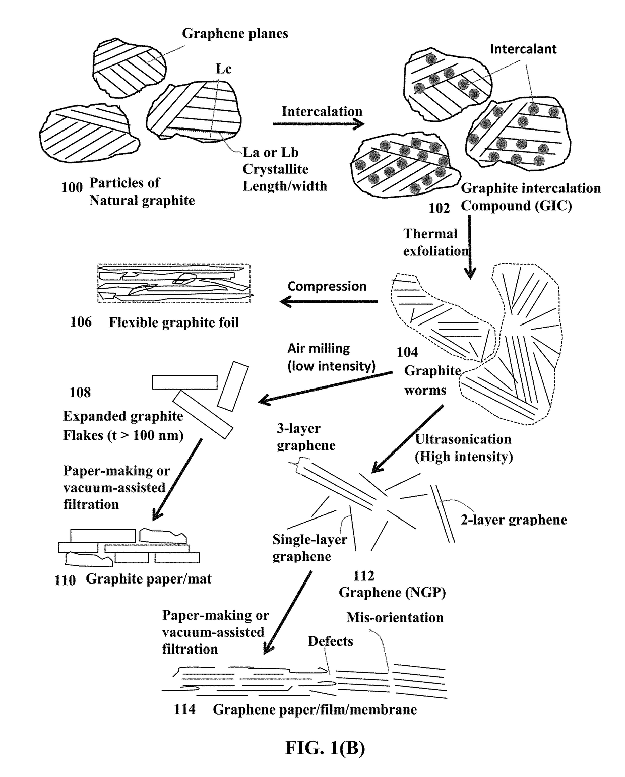
[0178]Chopped graphite fibers with an average diameter of 12 μm and natural graphite particles were separately used as a starting material, which was immersed in a mixture of concentrated sulfuric acid, nitric acid, and potassium permanganate (as the chemical intercalate and oxidizer) to prepare graphite intercalation compounds (GICs). The starting material was first dried in a vacuum oven for 24 h at 80° C. Then, a mixture of concentrated sulfuric acid, fuming nitric acid, and potassium permanganate (at a weight ratio of 4:1:0.05) was slowly added, under appropriate cooling and stirring, to a three-neck flask containing fiber segments. After 5-16 hours of reaction, the acid-treated graphite fibers or natural graphite particles were filtered and washed thoroughly with deionized water until the pH level of the solution reached 6. After being dried at 100° C. overnight, the resulting graphite intercalation compound (GIC)...

example 2a

on of Metals into Graphene Foam Pores

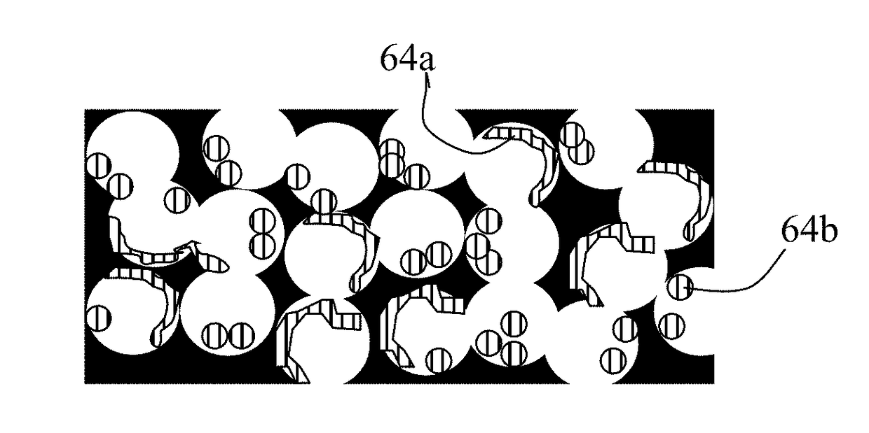
[0182]For incorporation of higher melting point metals (e.g. Au, Ag, Ni, Co, Mn, Fe, and Ti) as a lithium- or sodium-attracting metal in a graphene foam, a small but controlled amount of the desired metal was deposited on the surfaces of graphene sheets using sputtering, physical vapor deposition, or chemical vapor deposition. It is not necessary to cover the entire graphene surface with metal. These lightly metal-coated graphene sheets are then dispersed in the liquid medium to form a suspension, which is then coated to form a film and then heat treated to form a graphene foam.

[0183]For incorporation of lower melting metals, such as Mg, Zn, Na, K, and Sn, metal melt impregnation or electrochemical infiltration (plating) was implemented after the graphene foam was formed. It may be noted that electrochemical method is applicable to all metals, not just low-melting ones.

[0184]We have observed that it is easier for the single-layer graphene wall-ba...


PUM

PropertyMeasurementUnit
densityaaaaaaaaaa
pore sizeaaaaaaaaaa
densityaaaaaaaaaa

Abstract

Provided is a lithium or sodium metal battery having an anode, a cathode, and a porous separator and / or an electrolyte, wherein the anode contains a graphene-metal hybrid foam composed of multiple pores, pore walls, and a lithium- or sodium-attracting metal residing in the pores; wherein the metal is selected from Au, Ag, Mg, Zn, Ti, Na (or Li), K, Al, Fe, Mn, Co, Ni, Sn, V, Cr, or an alloy thereof and is in an amount of 0.1% to 90% of the total hybrid foam weight or volume, and the pore walls contain single-layer or few-layer graphene sheets, wherein graphene sheets contain a pristine graphene or non-pristine graphene selected from graphene oxide, reduced graphene oxide, graphene fluoride, graphene chloride, graphene bromide, graphene iodide, hydrogenated graphene, nitrogenated graphene, doped graphene, chemically functionalized graphene, or a combination thereof.

Description

FIELD OF THE INVENTION[0001]The present invention relates generally to the field of alkali metal battery (e.g. lithium metal battery or sodium metal battery) and, more particularly, to a lithium or sodium metal secondary battery having a graphene / metal hybrid foam-based electrode and a process for producing this electrode and battery.BACKGROUND OF THE INVENTIONA Critical Review on Alkali Metal Secondary Batteries[0002]Rechargeable lithium-ion (Li-ion) and lithium metal batteries (e.g. Li-sulfur, Li metal-air, and lithium-metal oxide batteries) are considered promising power sources for electric vehicle (EV), hybrid electric vehicle (HEV), and portable electronic devices, such as lap-top computers and mobile phones. Lithium as a metal element has the highest capacity (3,861 mAh / g) compared to any other metal. Hence, in general, Li metal batteries have a significantly higher energy density than lithium ion batteries. Similarly, Na metal batteries have a higher energy than correspondin...

Claims


Application Information

Patent Timeline
Patent Type & Authority Applications(United States)
IPC IPC(8): H01M4/133H01M10/054H01M4/36H01M4/38H01M10/0525H01M4/02
CPCH01M4/133H01M4/364H01M4/38H01M10/0525H01M2220/30H01M2004/027H01M2004/021H01M2220/20H01M10/054H01M4/1393C01B32/198C01B32/184C01B32/192Y02E60/10H01M4/134H01M4/62H01M4/808H01M10/052Y02T10/70
Inventor ZHAMU, ARUNAJANG, BOR Z.
Owner GLOBAL GRAPHENE GRP INC
Why Eureka
Try Eureka