

Fuel-cell system and method of generating energy from crude fuel
a fuel cell and crude fuel technology, applied in the field of fuel cell systems and a method of generating energy from crude fuel, can solve the problems of limiting the working efficiency and output power density affecting the efficiency of the fuel cell, etc., and achieves high surface area, high efficiency, and high efficiency.
- Summary
- Abstract
- Description
- Claims
- Application Information
AI Technical Summary
Benefits of technology
Problems solved by technology
Method used
Image

Examples
example 1
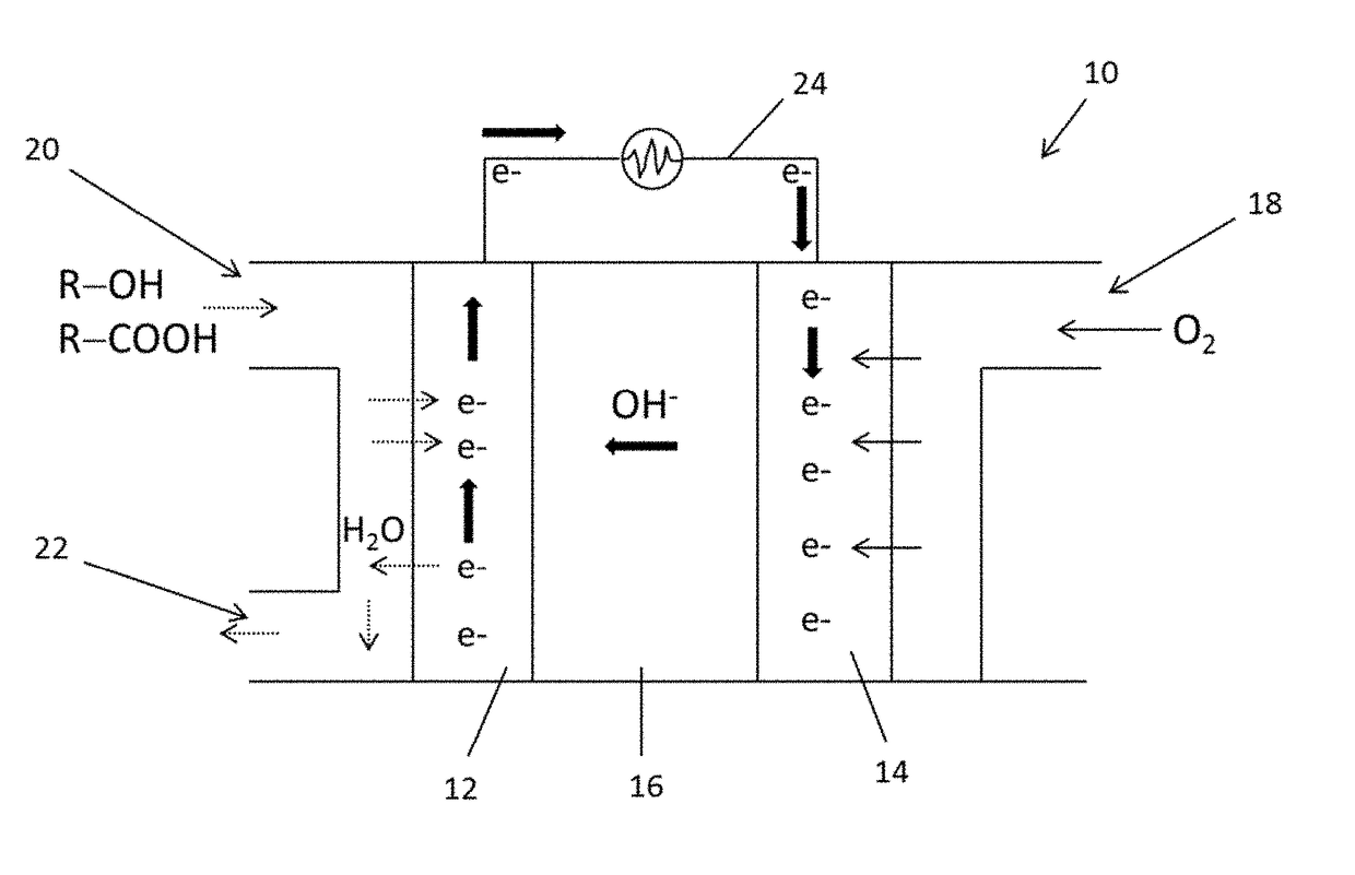
Doped Mesoporous Carbon as Metal-Free Cathode Catalysts for Direct Biorenewable Alcohol Fuel Cells
[0115]Material Preparation
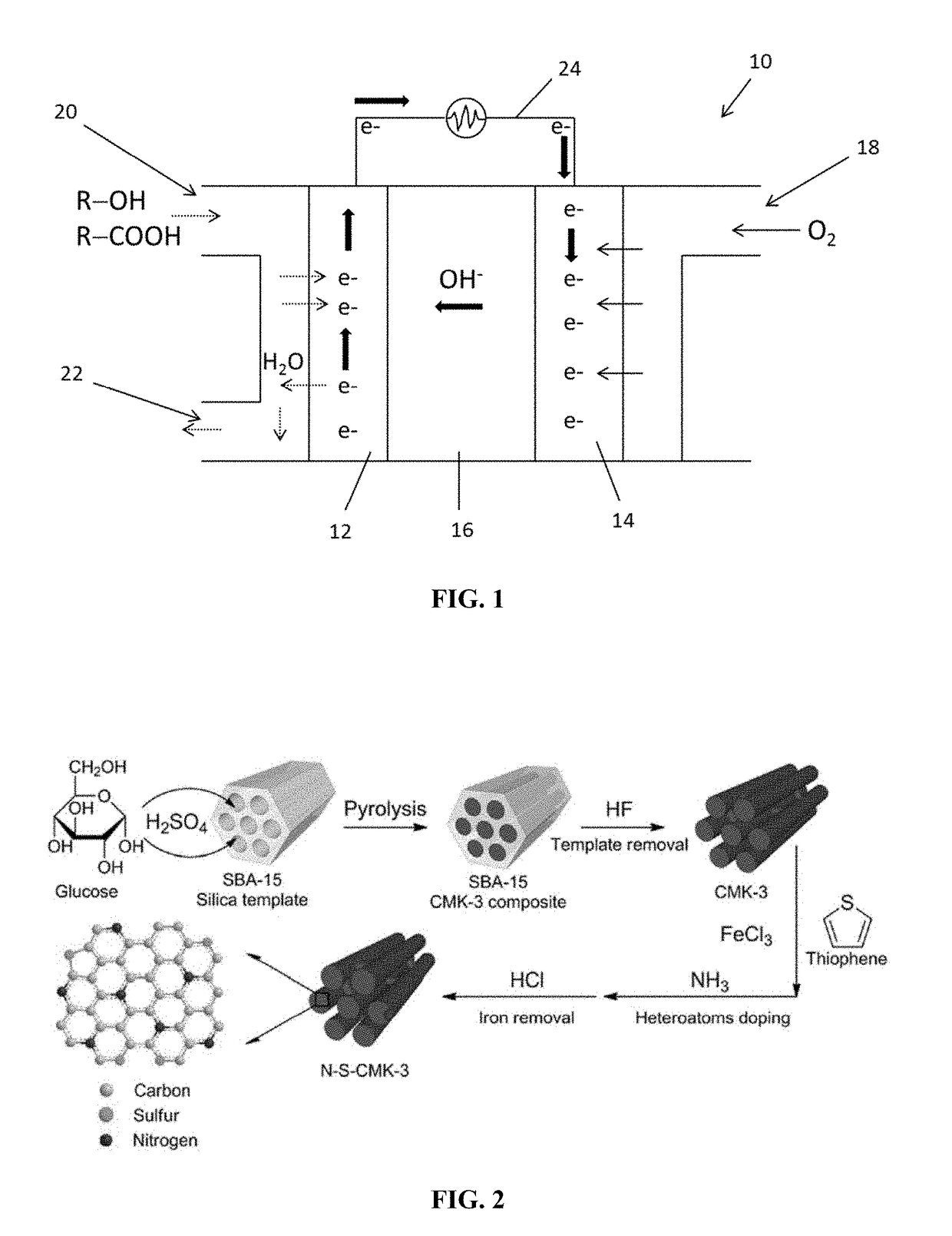
[0116]Synthesis of CMK-3 Used SBA-15 as the Template
[0117]For the synthesis of SBA-15 (Zhao et al., “Triblock Copolymer Syntheses of Mesoporous Silica with Periodic 50 to 300 Angstrom Pores,”Science 279:548 (1998), which is hereby incorporated by reference in its entirety), Pluoronic P123 (5.0 g) was dissolved in a hydrochloric solution (190 mL, 1.6 M) with 350 rpm stirring at 35° C. After the dissolution of P123, tetraethyl orthosilicate (11.0 g) was added into the solution and stirred at 35° C. for another 24 hours. The solution was then moved into a polytetrafluoroethylene bottle for an additional 24 hour treatment at 100° C. After that, the solid was filtered and washed with deionized water (18.2 Me) and dried in an oven overnight. A final calcination in air at 550° C. for 6 hours was used to remove the surfactant. Then, SBA15 (2.8 g) was mixed with deioniz...
example 2
o-Oil Fuel Cell
Experimental
[0168]Chemicals
[0169]Palladium (II) nitrate dehydrate, silver nitrate, gold (III) chloride, polytetrafluoroethylene (PTFE), 1-propanol (99.5%), sodium borohydride (99%), sodium citrate dehydrate (99%), glucose (99%), sucrose (99%), potassium hydroxide (85%), and potassium sulfate (99%) were purchased from Sigma-Aldrich. Carboxyl-group functionalized multi-walled carbon nanotubes (8-15 nm outer diameter, 0.5-2 μm length) were obtained from Cheaptubes Inc. The catalyst 4020 was bought from Actna, Inc. Levoglucosan, cellobiosan, and maltosan were obtained from Carbosynth. Xylose was purchased from Thermo Fisher Scientific. Stage fraction 2 bio-oil was obtained from Iowa State University BioCentury Research Farm. All the chemicals were used as received without further purifications.
[0170]Catalyst Synthesis and Physical Characterizations
[0171]Carbon nanotube supported Pd, Pt, Ag, and Au nanoparticles were synthesized by an aqueous phase reduction method (Qi et ...
example 3
nge Membrane-Free Direct Alcohol Fuel Cell Chemicals
[0203]Palladium (II) nitrate dihydrate, silver nitrate, 1-propanol (99.5%), potassium sulfate (99%), polytetrafluoroethylene (PTFE), sodium borohydride (99%), and sodium citrate dehydrate (99%) were purchased from Sigma-Aldrich. High purity glycerol (99.8%) was bought from Thermo Fisher Scientific. Carboxyl-group functionalized multi-wall carbon nanotube (8-15 nm outer diameter, 0.5-2 μm length) was received from Cheaptubes Inc. The catalyst 4020 was bought from Actna, Inc. PTFE thin films (0.22, 0.45, 1.0 μm) were purchased from Membrane Solutions. All the chemicals were used as received without further purifications.
[0204]Synthesis of PdAg / CNT Catalyst
[0205]PdAg / CNT (20 wt %) was prepared via a self-developed aqueous phase reduction method (Qi et al., “Electrocatalytic Selective Oxidation of Glycerol to Tartronate on Au / C Anode Catalysts in Anion Exchange Membrane Fuel Cells with Electricity Cogeneration,”Applied Catalysis B: Env...
PUM
| Property | Measurement | Unit |
|---|---|---|
| Diameter | aaaaa | aaaaa |
| Temperature | aaaaa | aaaaa |
| Temperature | aaaaa | aaaaa |
Abstract
Description
Claims
Application Information