Fast-chargeable lithium battery

a lithium battery, fast-charge technology, applied in the direction of cell components, electrochemical generators, cell component details, etc., to achieve the effect of improving the structural integrity of the porous structur

Active Publication Date: 2019-12-12
GLOBAL GRAPHENE GRP INC
View PDF3 Cites 24 Cited by
  • Summary
  • Abstract
  • Description
  • Claims
  • Application Information

AI Technical Summary

Benefits of technology

[0036]In some embodiments, the porous framework structure contains a conducting foam, which can be a closed-cell foam or open-cell foam. The open-cell foam is preferred. However, the pores preferably contain mesoscaled pores having a pore size from 2 nm to 100 nm, more preferably from 2 nm to 50 nm, which are more effective in holding certain lithium ion-capturing species.
[0037]In some embodiments, the electron-conducting porous structure has pore walls comprising an electron-conducting material selected from carbon nanotubes, carbon nanofibers, graphene sheets, expanded graphite platelets, carbon fibers, graphite fibers, graphite particles, needle coke, mesocarbon microbeads, carbon particles, carbon black, acetylene black, activated carbon particles, or a combination thereof. Multiple fibers or particles of electron-conducting materials optionally may be bonded by a resin binder (0.1%-10%) to improve the structural integrity of the porous structure. Preferably, the electron-conducting porous structure contains a graphene foam.

Problems solved by technology

Unfortunately, upon repeated charges and discharges, the lithium metal resulted in the formation of dendrites at the anode that ultimately caused internal shorting, thermal runaway, and explosion.
As a result of a series of accidents associated with this problem, the production of these types of secondary batteries was stopped in the early 1990's giving ways to lithium-ion batteries.
Even now, cycling stability and safety concerns remain the primary factors preventing the further commercialization of Li metal batteries (e.g. Lithium-sulfur and Lithium-transition metal oxide cells) for EV, HEV, and microelectronic device applications.
Again, cycling stability and safety issues of lithium metal rechargeable batteries are primarily related to the high tendency for Li metal to form dendrite structures during repeated charge-discharge cycles or overcharges, leading to internal electrical shorting and thermal runaway.
This thermal runaway or even explosion is caused by the organic liquid solvents used in the electrolyte (e.g. carbonate and ether families of solvents), which are unfortunately highly volatile and flammable.
However, despite these earlier efforts, no rechargeable Li metal batteries have succeeded in the market place.
This is likely due to the notion that these prior art approaches still have major deficiencies.
For instance, in several cases, the anode or electrolyte structures designed for prevention of dendrites are too complex.
In others, the materials are too costly or the processes for making these materials are too laborious or difficult.
Although lithium-ion (Li-ion) batteries are promising energy storage devices for electric drive vehicles, state-of-the-art Li-ion batteries have yet to meet the cost, safety, and performance targets.
Despite the notion that there is significantly reduced propensity of forming dendrites in a lithium-ion cell (relative to a lithium metal cell), the lithium-ion cell has its own intrinsic safety issue.
Although ILs were suggested as a potential electrolyte for rechargeable lithium batteries due to their non-flammability, conventional ionic liquid compositions have not exhibited satisfactory performance when used as an electrolyte likely due to several inherent drawbacks: (a) ILs have relatively high viscosity at room or lower temperatures; thus being considered as not amenable to lithium ion transport; (b) For Li—S cell uses, ILs are capable of dissolving lithium polysulfides at the cathode and allowing the dissolved species to migrate to the anode (i.e., the shuttle effect remains severe); and (c) For lithium metal secondary cells, most of the ILs strongly react with lithium metal at the anode, continuing to consume Li and deplete the electrolyte itself as charges and discharges are repeated.
These factors lead to relatively poor specific capacity (particularly under high current or high charge / discharge rate conditions, hence lower power density), low specific energy density, rapid capacity decay and poor cycle life.
Furthermore, ILs remain extremely expensive.
Consequently, as of today, no commercially available lithium battery makes use of an ionic liquid as the primary electrolyte component.
However, the current Li-sulfur experimental cells of industry leaders in sulfur cathode technology have a maximum cell specific energy of 250-400 Wh / kg (based on the total cell weight), far less than what could be obtained in real practice.
In summary, despite its considerable advantages, the rechargeable lithium metal cell in general and the Li—S cell and the Li-Air cell in particular are plagued with several major technical problems that have hindered its widespread commercialization:(1) Conventional lithium metal secondary cells (e.g., rechargeable Li metal cells, Li—S cells, and Li-Air cells) still have dendrite formation and related internal shorting and thermal runaway issues.
Also, conventional Li-ion cells still make use of significant amounts of flammable liquids (e.g. propylene carbonate, ethylene carbonate, 1,3-dioxolane, etc.) as the primary electrolyte solvent, risking danger of explosion;(2) The tendency for a lithium metal anode to form dendrites is presumably caused by the low deposition rate of the returning lithium ions onto the Cu foil current collector (and the metal film previously deposited thereon) during the recharge step.
This also implies that a lithium metal cell cannot be recharged rapidly;(3) The Li—S cell tends to exhibit significant capacity degradation during discharge-charge cycling.
This is mainly due to the high solubility of the lithium polysulfide anions formed as reaction intermediates during both discharge and charge processes in the polar organic solvents used in electrolytes.
In addition, the solid product that precipitates on the surface of the positive electrode during discharge can become electrochemically irreversible, which also contributes to active mass loss.More generally speaking, a significant drawback with cells containing cathodes comprising elemental sulfur, organosulfur and carbon-sulfur materials relates to the dissolution and excessive out-diffusion of soluble sulfides, polysulfides, organo-sulfides, carbon-sulfides and / or carbon-polysulfides (hereinafter referred to as anionic reduction products) from the cathode into the rest of the cell.
This process leads to several problems: high self-discharge rates, loss of cathode capacity, corrosion of current collectors and electrical leads resulting in loss of electrical contact to active cell components, fouling of the anode surface giving rise to malfunction of the anode, and clogging of the pores in the cell membrane separator which leads to loss of ion transport and large increases in internal resistance in the cell.
Some interesting cathode developments have been reported recently to contain lithium polysulfides; but, their performance still fall short of what is required for practical applications.
Although solid electrolytes are effective in addressing the lithium metal dendrite and flammability issues, conventional solid-state electrolytes have the following major deficiencies: low lithium ion conductivities (typically −4 S / cm, more typically −5 S / cm, and further more typically −6 S / cm), difficulty in making solid-state electrolyte (high temperature sintering typically required) and implementing it in a battery cell, extreme brittleness, no flexibility (hence, not being compliant and being in poor ionic contact with the anode and / or cathode and, hence, poor active material utilization efficiency), and high costs.

Method used


Image

  • Fast-chargeable lithium battery
  • Fast-chargeable lithium battery
  • Fast-chargeable lithium battery

Examples


example 1

of Sulfonated Polyaniline (S-PANi)

[0128]The chemical synthesis of the S-PANi polymers was accomplished by reacting polyaniline with concentrated sulfuric acid. The procedure was similar to that used by Epstein, et al. (U.S. Pat. No. 5,109,070, Apr. 28, 1992). The resulting S-PANi can be represented by the following Formula 1, with R1, R2, R3, and R4 group being H, SO3 or SO3H (R5=H) with the content of the latter two being varied between 30% and 75% (i.e., the degree of sulfonation varied between 30% and 75%).

[0129]The lithium ion conductivity of these SO3− or SO3H-based S-PANi compositions was in the range from 8.5×10⁻⁵ S / cm to 4.6×10⁻³ S / cm and their electron conductivity in the range from 0.1 S / cm to 0.5 S / cm when the degree of sulfonation was from approximately 30% to 75% (with y being approximately 0.4-0.6).

[0130]The porous framework for the lithium ion reservoir layer was obtained by dissolving S-PANi in water to form a polymer-water solution, which was freeze-dried to obtain ...

example 2

on of Electrically Non-Conducting Polymers

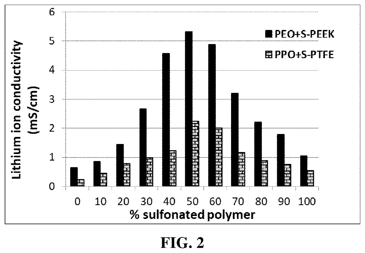
[0133]Polytetrafluoroethylene (PTFE), polysulfone (PSf), poly (ether ether ketone) (PEEK), polyimide (PI), and styrene-butadiene copolymers (SB) were separately immersed in a concentrated sulfuric acid (95%+5% water) at 65-90° C. for 4-48 hours to obtain sulfonated polymers. These sulfonated polymers were found to be electrically insulating (−8 S / cm), but lithium ion-conducting (typically 3×10⁻⁵ S / cm-4.5×10⁻³ S / cm, depending on the degree of sulfonation).

[0134]These highly sulfonated polymers, along with some desired amounts of baking soda as a blowing agent, were dissolved in water to form solutions, which were cast to form thin films onto a glass substrate and heated at 100° C.-250° C. for 0.3 to 5 minutes to produce porous structures. In one additional sample, graphene oxide sheets (graphene / polymer ratio= 1 / 10) were added to the sulfonated PEEK / baking soda solution to form a slurry, which was cast, dried, and heat-treated at 300° C. for ...

example 3

on of Graphene Oxide Sheets (GO) and Reduced Graphene Oxide (RGO) Foam

[0135]Chopped graphite fibers with an average diameter of 12 μm and natural graphite particles were separately used as a starting material, which was immersed in a mixture of concentrated sulfuric acid, nitric acid, and potassium permanganate (as the chemical intercalate and oxidizer) to prepare graphite intercalation compounds (GICs). The starting material was first dried in a vacuum oven for 24 h at 80° C. Then, a mixture of concentrated sulfuric acid, fuming nitric acid, and potassium permanganate (at a weight ratio of 4:1:0.05) was slowly added, under appropriate cooling and stirring, to a three-neck flask containing fiber segments. After 5-16 hours of reaction, the acid-treated graphite fibers or natural graphite particles were filtered and washed thoroughly with deionized water until the pH level of the solution reached 6. After being dried at 100° C. overnight, the resulting graphite intercalation compound ...


PUM

PropertyMeasurementUnit
pore sizeaaaaaaaaaa
pore sizeaaaaaaaaaa
temperatureaaaaaaaaaa

Abstract

Provided is a lithium secondary battery containing an anode, a cathode, a porous separator disposed between the anode and the cathode, an electrolyte, and a lithium ion reservoir disposed between the anode and the porous separator and configured to receive lithium ions from the cathode when the battery is charged and enable the lithium ions to enter the anode in a time-delayed manner, wherein the reservoir comprises a conducting porous framework structure having pores (pore size from 1 nm to 500 μm) and lithium-capturing groups residing in the pores, wherein the lithium-capturing groups are selected from (a) redox forming species that reversibly form a redox pair with a lithium ion; (b) electron-donating groups interspaced between non-electron-donating groups; (c) anions and cations wherein the anions are more mobile than the cations; or (d) chemical reducing groups that partially reduce lithium ions from Li+1 to Li, wherein 0<δ<1.

Description

FIELD OF THE INVENTION[0001]The present invention provides a fast-chargeable lithium-ion battery and a lithium metal battery (having lithium metal or metal alloy as the main anode active material).BACKGROUND[0002]Rechargeable lithium-ion (Li-ion) and rechargeable lithium metal batteries (e.g. lithium-sulfur, lithium-selenium, and Li metal-air batteries) are considered promising power sources for electric vehicle (EV), hybrid electric vehicle (HEV), and portable electronic devices, such as lap-top computers and mobile phones. Lithium as a metal element has the highest lithium storage capacity (3,861 mAh / g) compared to any other metal or lithium intercalation compound as an anode active material (except Li4.4Si, which has a specific capacity of 4,200 mAh / g). Hence, in general, Li metal batteries (having a lithium metal anode) have a significantly higher energy density than lithium-ion batteries (e.g. having a graphite anode).[0003]Historically, rechargeable lithium metal batteries wer...

Claims


Application Information

Patent Timeline
Patent Type & Authority Applications(United States)
IPC IPC(8): H01M4/60H01M10/052H01M10/0569H01M10/0568H01M4/134H01M4/36H01M4/62H01M4/80H01M4/66H01M4/38H01M2/16H01M50/414H01M50/417H01M50/423H01M50/491
CPCH01M4/134H01M4/382H01M4/606H01M10/052H01M4/808H01M10/0569H01M4/625H01M2300/0037H01M2/1653H01M10/0568H01M2004/027H01M4/663H01M4/366H01M4/386H01M4/38H01M4/483H01M2300/0094Y02E60/10H01M50/417H01M50/414H01M50/491H01M50/423
Inventor HE, HUILIU, CHUEHZHAMU, ARUNAJANG, BOR Z.
Owner GLOBAL GRAPHENE GRP INC
Why Eureka
Try Eureka