Self-grown monopoly compact grit

a compact grit and self-grown technology, applied in the field of self-grown monopoly compact grit, can solve the problems of wasting effort, presenting several problems, and using the hpht process is still a very expensive operation, and achieves the effects of cost saving, good economic benefits, and convenient us

Inactive Publication Date: 2003-03-06
CHO HYUN SAM +2
View PDF0 Cites 12 Cited by
  • Summary
  • Abstract
  • Description
  • Claims
  • Application Information

AI Technical Summary

Benefits of technology

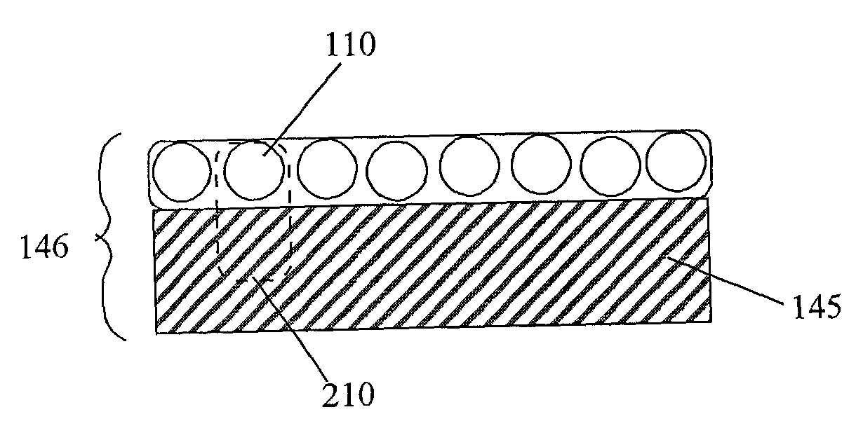
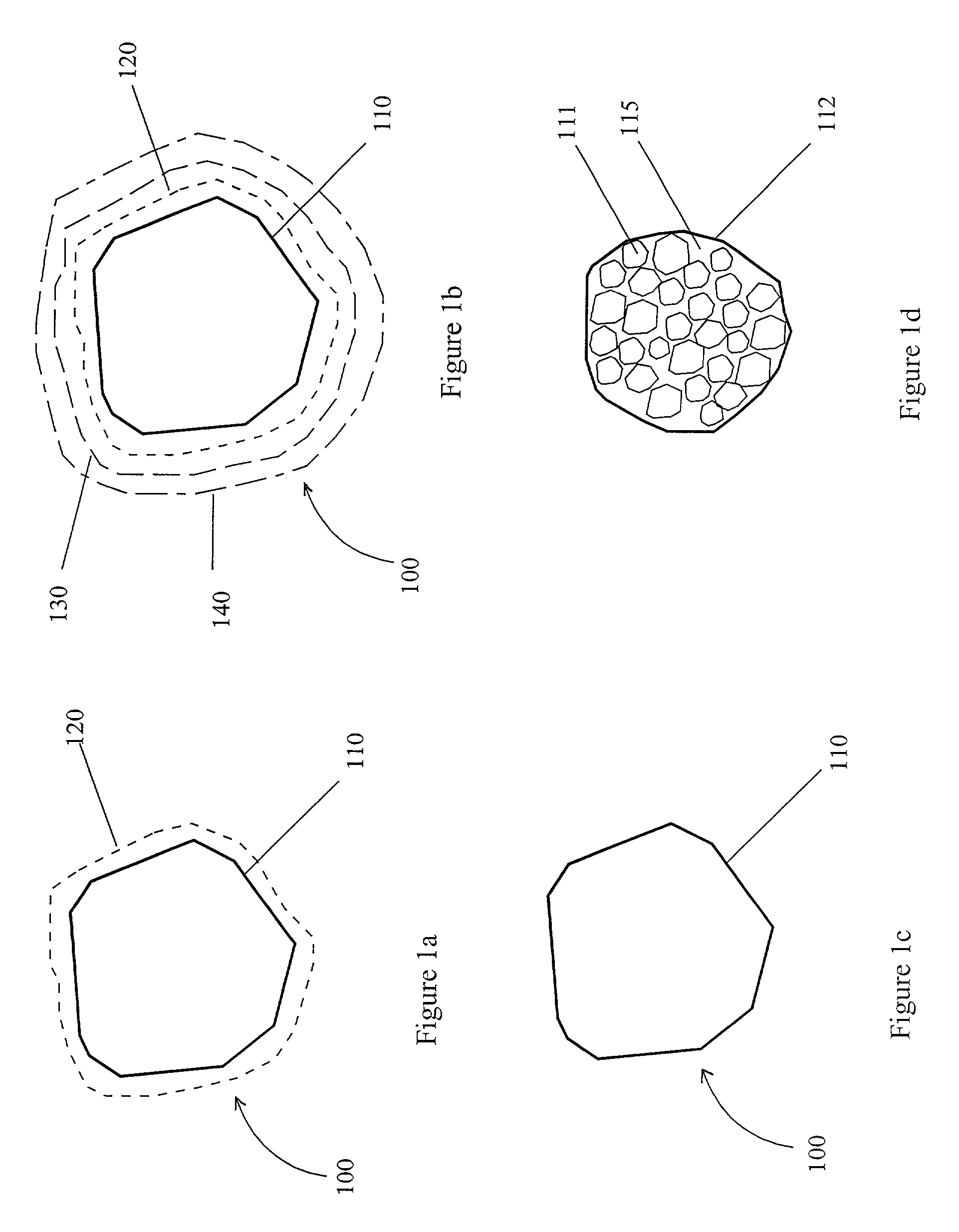
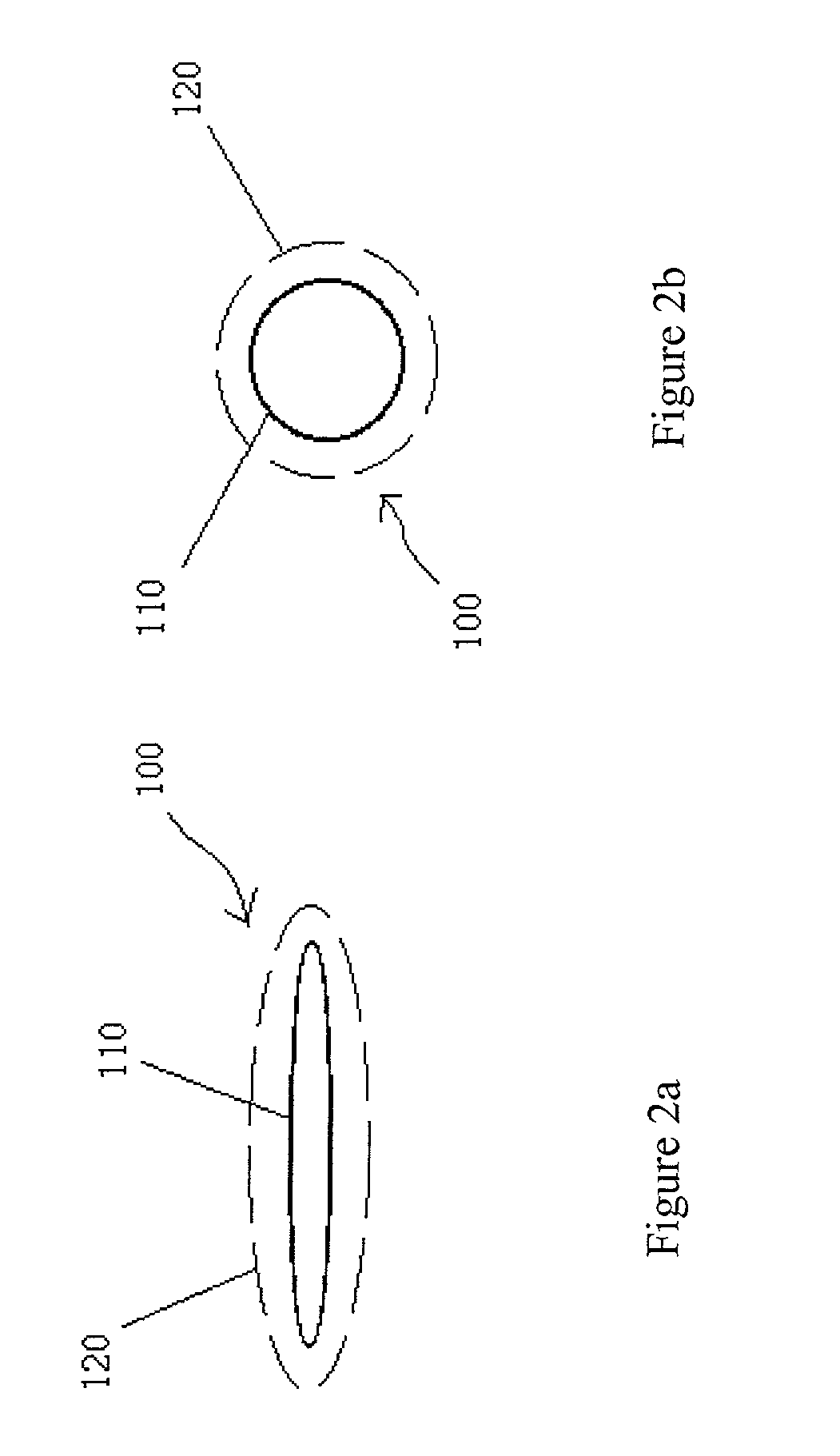
0083] In summary, the improved HPHT process of the present invention provides a method of achieving a desirable morphology for a monopoly compact grit. The improved process also includes proper preparation of a monopoly precursor material followed by the application of optimum Ptt (pressure-temperature-time) cycles during the HPHT synthesis process. The resulting monopoly compact grits, of varying composition, including diamond crystals, diamond seed-PCD grits, non-diamond seed-diamond grits, non-diamond seed PCD grits, and PCDBN grits, as fabricated in various desired shapes by the process of the present invention, are of particularly great value when incorporated into tools for industrial applications such as saw blades, drill

Problems solved by technology

A great deal of effort has been expended to increase the economy of preparing diamond grits under the HPHT conditions, however, commercial production of synthetic diamond grits, using the HPHT process is still a very expensive operation.
However, it presents several problems.
First, the synthesis reaction takes a very long time, thus increasing the operation costs of the apparatus required to affect the carbon to diamond transition.
Additionally, because the method requires a temperature gradient to be created in a relatively small sample chamber, the number of crystals which can be produced in a single reaction is small.
Therefore, the small crystal yield increases the production costs of each crystal.
The "thin film solvent method", solves many of the problems inherent in the "temperature gradient method", but increases the frequency of other problems such as spontaneous nucleation.
Such problems give rise to great difficulty in synthesizing crystals of a large grain size, and make the crystals produced inferior in quality as they may be contaminated with many inclusions.
However, the manufacturing cost for growing larger diamond in the HPHT process is higher because of the required longer reaction/synthesis time and a relatively lower yield under HPHT conditions.
Such a process is cost and quality prohibitive from being utilized on a mass production scale.
Although the current HPHT diamond

Method used


Image

  • Self-grown monopoly compact grit
  • Self-grown monopoly compact grit
  • Self-grown monopoly compact grit

Examples


example 1

[0087] The nickel coating utilized was first carried out by a non-electrolytical process, using a solution of NiCl.sub.2.6H.sub.2O, NaH.sub.2PO.sub.2.H.sub.2O, Na.sub.2C.sub.4H.sub.4O.sub.4.6H.sub.2O, and H.sub.3BO.sub.3 at a temperature of 70.about.90.degree. C. for about 20 minutes. This pre-Ni coated seed material was then nickel coated electrolytically, in a Ni-electrolytic bath in order to achieve a 100 .mu.m thick coating.

[0088] This example employs a triple coating of Ni-Fe-Ni, another nickel coating was put on by electrolysis and then a thin layer of fine iron powder was applied by a spray granulation coating process which can provide a loosely packed powder over the nickel layer. Finally, a third nickel coating was electrolytically applied.

[0089] A polylayer precursor was prepared of a slurry of 1.about.3 .mu.m diamond powder mixed with 1.about.5 .mu.m of metal powder binder (Fe, Ni, or Co) per the composition indicated in Table 1. The metal coated seed crystals were then c...

example 2

[0092] The same process as in Example 1 was used, except for the variations as shown in Table 1, such as coating thickness, cobalt instead of iron coating, and use of a PEG binder in the polylayer precursor. The recovered monopoly grits of Example 2 show signs of new PCD growth 150, similar to that shown in FIG. 9b.

examples 3-8

[0093] The same process as in Examples 1 and 2 were used with the variations as shown in Table 1. The resulting monopoly compact grits are shown in FIGS. 9b through 9e.

1TABLE 1 Coating Polylayer Precursor Polylayer Monopoly Example Mono seed size Type of thickness composition thickness compact grit No (mesh) Coating (.mu.m) (vol %) (.mu.m) Result 1 Diamond Ni 100 1.about.3 .mu.m 200 70 / 80 Ni--Fe--Ni 40-10-40 diamond (100%) 70 / 80 mesh 2 Diamond Ni 50 1.about.3 .mu.m 250 80 / 100 Ni--Co--Ni 20-5-20 diamond (80%) 80 / 100 mesh Binder (20%) 3 Diamond Ni--Ti 50-2 1.about.3 .mu.m 300 100 / 120 Ni--Fe--Ni 40-10-50 diamond (100%) 100 / 120 mesh 4 CBN Ti--Al 5-5 1.about.3 .mu.m 200 80 / 100 Ti--Si 5-1 CBN (100%) 80 / 100 mesh 5 Ni-rod No coating 0 1.about.3 .mu.m 300 Needle-shape diamond 1000 .times. 100 .mu.m 6 Diamond 1.about.3 .mu.m 300 120 / 140 Ni--Co--Ni 40-5-40 diamond (100%) 80 / 100 Ni--Co--Ni 20-5-20 7 CBN Ni--Ti 40-2 1.about.3 .mu.m 200 80 / 100 diamond (80%) 80 / 100 mesh Binder (20%) 8 Diamond Ni--...


PUM

PropertyMeasurementUnit
Angleaaaaaaaaaa
Percent by massaaaaaaaaaa
Percent by volumeaaaaaaaaaa

Abstract

A self-grown monopoly compact grit and high pressure, high temperature process for preparing the same. The high pressure, high temperature sintered/synthesized monopoly compact grit is used in various industrial tools such as saw blades, grinding wheels, cutting tools and drill bits. Further, the monopoly compact grit of the present invention is produced from a seed of a mono-crystal of diamond or cubic boron nitride surrounded by either a self-grown crystal layer or an integrally bonded poly-crystalline sintered compact layer. The self-grown crystal layer is a new grown crystal structure where the seed crystal grows into a new phase through a normal diamond or cubic boron nitride synthesis process in the presence of a catalyst metal solvent. The compact layer is composed of about 50 to about 90 volume percent of diamond or cubic boron nitride, a typical binder material, which is a catalyst for crystal-to-crystal bonding, and a cementing agent which is a binding agent capable of forming stable carbide and nitride bonds.

Description

THE FIELD OF THE INVENTION[0001] The present invention relates generally to methods of forming synthetic diamond or polycrystalline diamond (PCD). More specifically, the present invention relates to a new, high pressure-high temperature (HPHT) sintered / synthesized, self-grown, monopoly compact grit and methods of preparation thereof.[0002] Diamond is a gemstone known for its rarity and beauty. As an industrial material, its superior hardness and wear resistance make diamond a preferred material in a variety of applications. For example, diamond is used extensively as an abrasive in polishing operations. Additionally, diamond-tipped drills and cutting tools are indispensable in shaping and cutting extremely hard materials such as sintered carbide and quartz. In order to help meet the industrial demand for these types of tools, a number of techniques have been developed for the production of synthetic diamonds. While natural diamond is still used in many industrial applications, diamo...

Claims


Application Information

Patent Timeline
IPC IPC(8): B01J3/06B22F1/17B22F1/18C04B35/5831C04B35/645
CPCB01J3/062Y10T428/30B01J2203/062B01J2203/063B01J2203/0635B01J2203/0645B01J2203/0655B01J2203/066B01J2203/068B22F1/025C04B35/52C04B35/5626C04B35/5831C04B35/6303C04B35/645C04B2235/386C04B2235/402C04B2235/404C04B2235/405C04B2235/427C04B2235/428C04B2235/5276C04B2235/528C04B2235/5436B01J2203/061B22F1/17B22F1/18
Inventor CHO, HYUN SAMCHEN, JOHNHAN, KYUNG YUL
Owner CHO HYUN SAM
Why Eureka
Try Eureka