
Lithium metal-sulfur and lithium ion-sulfur secondary batteries containing a nano-structured cathode and processes for producing same

Active Publication Date: 2011-07-07
GLOBAL GRAPHENE GRP INC
View PDF20 Cites 191 Cited by
  • Summary
  • Abstract
  • Description
  • Claims
  • Application Information

AI Technical Summary

Benefits of technology

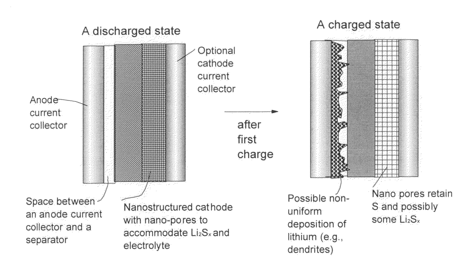
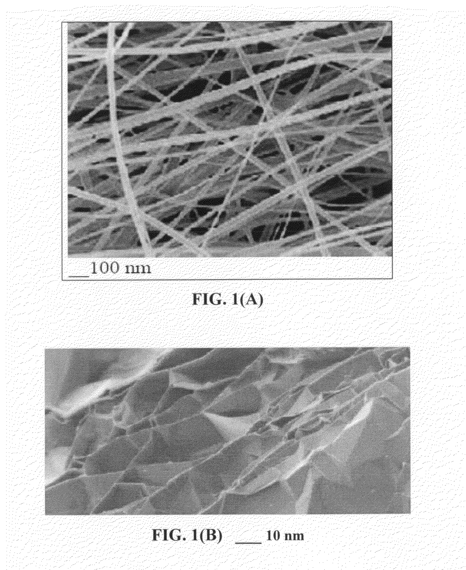
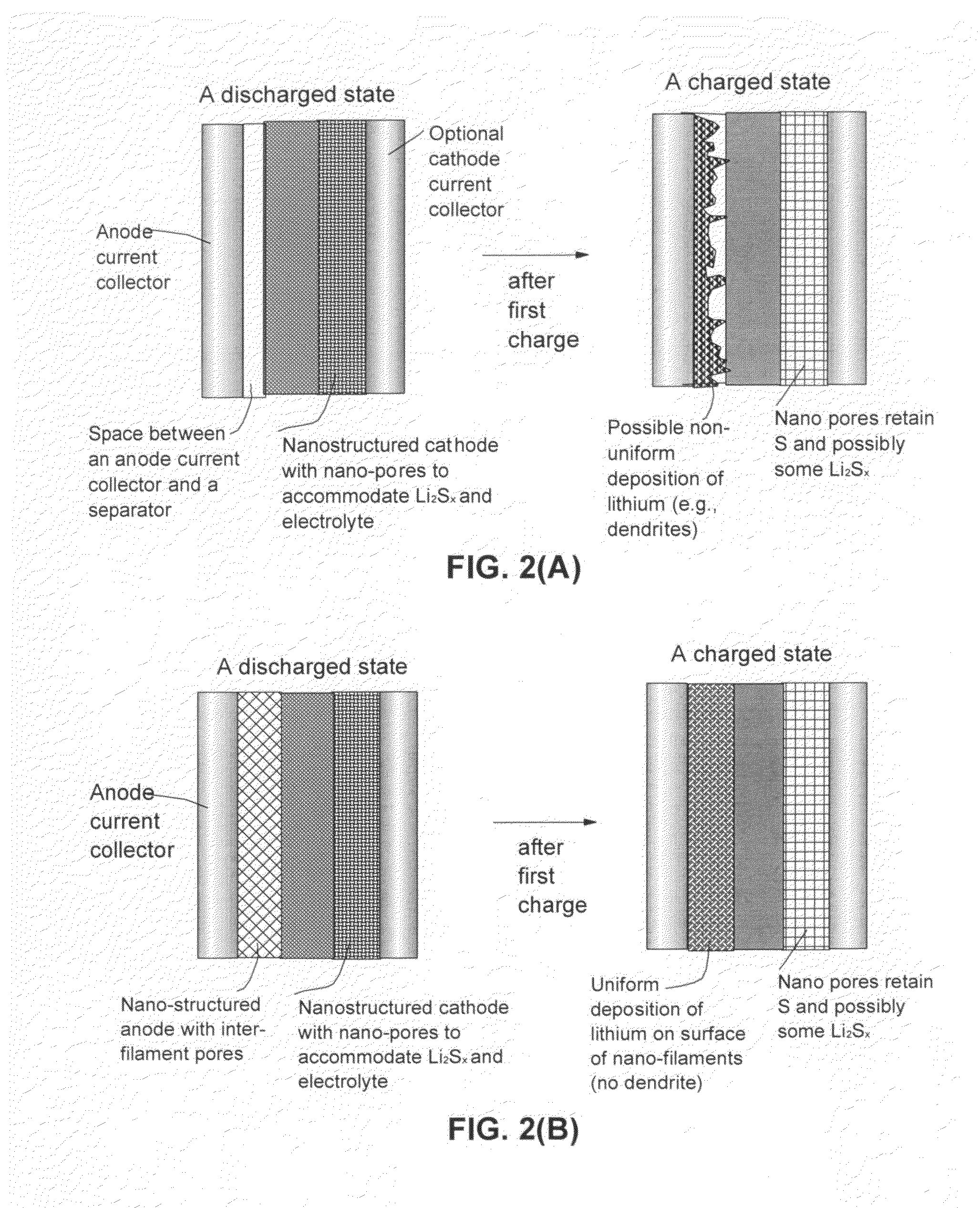
[0062]It may be noted that, as discussed earlier, Ji, et al [Ref. 26] reported a cathode based on nanostructured sulfur / mesoporous carbon materials that could exhibit stable and high reversible capacities (up to 1,320 mAh per gram of the cathode material) with good rate properties and cycling efficiency. However, the fabrication of the proposed highly ordered mesoporous carbon structure requires a tedious and expensive process that involves the utilization of a sacrificial template. Further, the cathode was made to contain elemental sulfur and, hence, required a lithium metal foil at the anode when the cell was made. Similarly, Zheng et al [Ref.21] used carbon nanotubes (CNTs) to form meso pores (10-60 nm), but also began with absorbing elemental sulfur in the pores when the cell was made, requiring the use of a lithium metal foil at the anode. The Li metal foil presents a challenging operation in a real world manufacturing environment. Neither Li, et al. nor Zhen, et al. recognized that non-CNT nano-filaments could be utilized to form nano-pores capable of retaining lithium polysulfide species comprising Li2Sx, where x=1-8 inclusive, allowing only Li+ to be shuttled back and forth between the cathode and the anode and preventing any intermediate Li2Sx from migrating to the anode. We were most surprising to observe that this nano-structured cathode approach effectively reduced or eliminated the capacity loss of the sulfur cathode during repeated charging and discharging cycles.
[0069]This nano-structured anode could be similar to those proposed by Burton et al [Ref.27] and Firsich [Ref.28] who used vapor-grown carbon nano-fibers (VG-CNFs) to support silicon coating obtained via chemical vapor deposition (CVD). In this case, the CVD silicon is an anode active material. Alternatively and more preferably, the anode structure may be a 3-D integrated structure (based on electro-spun conductive fibers, NGPs, CNTs, nano-wires, etc) for supporting Si nano particles or nano-coating as an anode active material, as disclosed in one of our earlier applications [e.g., Ref. 1]. The returning lithium ions in these earlier applications [Refs.1, 27, 28] were mostly inserted into the Si coating layer or particles. Although Si insertion causes volume swelling of Si coating or particles, nano-filaments enable stress-free volume expansion in the transverse direction, thereby avoiding the Si pulverization problem.
[0076](3) The interconnected network of filaments forms a continuous path for electrons, resulting in significantly reduced internal energy loss or internal heating. The nano-pores also imply the lithium-containing sulfide component inside the pores being nanometer-sized, enabling a fast cathode reaction. Hence, the cell is capable of being re-charged at a high rate. This is a highly beneficial feature for a battery that is intended for high power density applications such as electric vehicles.
[0077](4) The same type of integrated structure of conductive nano-filaments can be used as a support for the anode active material (e.g. Si in a lithium-ion battery or lithium metal in a Li metal cell), significantly simplifying the battery fabrication operations.
[0080](7) The nano-structured anode with thin, nano-scaled lithium coating is capable of quickly releasing lithium and thus capable of being discharged at a high rate.
[0086]The filaments may comprise nano graphene platelets with a thickness less than 10 nm. The filaments may comprise a nano graphene platelet containing nano-scale carbon nodules or bumps adhered to a surface of the graphene platelet. The carbon nodules or bumps serve as a spacer between individual graphene platelets to prevent NGPs from re-stacking or overlapping one another.

Problems solved by technology

Unfortunately, upon cycling, the lithium metal resulted in the formation of dendrites at the anode that ultimately caused unsafe conditions in the battery.
Even now, cycling stability and safety concerns remain the primary factors preventing the further commercialization of Li metal batteries for EV, HEV, and microelectronic device applications.
Specific cycling stability and safety issues of lithium metal rechargeable batteries are primarily related to the high tendency for Li to form dendrite structures during repeated charge-discharge cycles or an overcharge, leading to internal electrical shorting and thermal runaway.
However, despite these earlier efforts, no rechargeable Li metal batteries have yet succeeded in the market place.
This is likely due to the notion that these prior art approaches still have major deficiencies.
For instance, in several cases, the anode or electrolyte structures are too complex.
In others, the materials are too costly or the processes for making these materials are too laborious or difficult.
An amorphous carbon phase alone tends to exhibit a low electrical conductivity (high charge transfer resistance) and, hence, a high polarization or internal power loss.
These adverse effects result in a significantly shortened charge-discharge cycle life.
However, most of prior art composite electrodes have deficiencies in some ways, e.g., in most cases, less than satisfactory reversible capacity, poor cycling stability, high irreversible capacity, ineffectiveness in reducing the internal stress or strain during the lithium ion insertion and extraction cycles, and some undesirable side effects.
However, state-of-the-art Li-ion batteries have yet to meet the cost and performance targets.
In summary, despite its considerable advantages, the Li—S cell has been plagued with several problems that have hindered its widespread commercialization:(1) Conventional lithium metal cells still have dendrite formation and related internal shorting issues;(2) Sulfur or sulfur-containing organic compounds are highly insulating, both electrically and ionically.
Various carbon—sulfur composites have been used for this purpose, but only with limited success owing to the scale of the contact area.
This presents difficulties of electrolyte access.(4) The cell tends to exhibit significant capacity degradation on repeated discharge—charge cycling.
In addition, the solid product that precipitates on the surface of the positive electrode during discharge becomes electrochemically irreversible, which also contributes to active mass loss [Ref. 11].
To put it in a broader context, a significant drawback with cells containing cathodes comprising elemental sulfur, organosulfur and carbon-sulfur materials relates to the dissolution and excessive out-diffusion of soluble sulfides, polysulfides, organo-sulfides, carbon-sulfides and / or carbon-polysulfides (hereinafter referred to as anionic reduction products) from the cathode into the rest of the cell.
This process leads to several problems: high self-discharge rates, loss of cathode capacity, corrosion of current collectors and electrical leads leading to loss of electrical contact to active cell components, fouling of the anode surface giving rise to malfunction of the anode, and clogging of the pores in the cell membrane separator which leads to loss of ion transport and large increases in internal resistance in the cell.
However, much of the difficulty still remains at the cathode.
In the opposite approach (i.e. to contain the sulfides), some interesting cathode developments have been reported recently [Ref. 21-24]; but, their performance still fall short of what is required for practical applications.
However, a large polarization was observed, resulting in a very low operating voltage that reduces the energy density of cells.
The loading of active mass in the S-polymer composite is also limited (less than 55 wt %) owing to the low surface area of the conducting polymer.
This reduced energy density is a disadvantage of derivatives of organo-sulfur materials when utilized to overcome the dissolution problem.
However, the fabrication of the proposed highly ordered mesoporous carbon structure requires a tedious and expensive template-assisted process.

Method used


Image

  • Lithium metal-sulfur and lithium ion-sulfur secondary batteries containing a nano-structured cathode and processes for producing same
  • Lithium metal-sulfur and lithium ion-sulfur secondary batteries containing a nano-structured cathode and processes for producing same
  • Lithium metal-sulfur and lithium ion-sulfur secondary batteries containing a nano-structured cathode and processes for producing same

Examples


example 1

Conductive Web of Filaments from Electro-Spun PAA Fibrils

[0164]Poly (amic acid) (PAA) precursors for spinning were prepared by copolymerizing of pyromellitic dianhydride (Aldrich) and 4,4′-oxydianiline (Aldrich) in a mixed solvent of tetrahydrofurane / methanol (THF / MeOH, 8 / 2 by weight). The PAA solution was spun into fiber web using an electrostatic spinning apparatus schematically shown in FIG. 3. The apparatus consisted of a 15 kV d.c. power supply equipped with the positively charged capillary from which the polymer solution was extruded, and a negatively charged drum for collecting the fibers. Solvent removal and imidization from PAA were performed concurrently by stepwise heat treatments under air flow at 40° C. for 12 h, 100° C. for 1 h, 250° C. for 2 h, and 350° C. for 1 h. The thermally cured polyimide (PI) web samples were carbonized at 1,000° C. to obtain Sample c-PI-0 with an average fibril diameter of 67 nm. Such a web can be used to accommodate lithium sulfide, lithium d...

example 2

Conductive Web of Filaments from Electro-Spun PAN Fibrils and NGP-Containing PAN Fibrils

[0165]Suspension solutions were obtained by first preparing two solutions (A=solvent+NGPs and B=solvent+polymer) and then mixing the two solutions together to obtain the suspension solution. In the case of NGP-PAN fibril, the solvent used was N,N,-dimethyl formamide (DMF). For the preparation of Suspension A, the NGPs were added to a solvent and the resulting suspensions were sonicated to promote dispersion of separate NGPs in the solvent with a sonication time of 20 minutes. Suspension solution B was obtained by dissolving the polymer in the solvent with the assistance of heat (80° C. for DMF+PAN) and stirring action using a magnetic stirrer typically for 90 and 30 minutes, respectively. Suspensions A and B were then mixed together and further sonicated for 20 minutes to help maintain a good dispersion of NGPs in the polymer-solvent solution. An electrostatic potential of 10 kV was applied over ...

example 3

Preparation of NGP-Based Webs (Webs of NGPs and NGPs+CNFs)

[0168]Continuous graphite fiber yarns (Magnamite AS-4 from Hercules) were heated at 800° C. in a nitrogen atmosphere for 5 hours to remove the surface sizing. The yarns were cut into segments of 5 mm long and then ball-milled for 24 hours. The intercalation chemicals used in the present study, including fuming nitric acid (>90%), sulfuric acid (95-98%), potassium chlorate (98%), and hydrochloric acid (37%), were purchased from Sigma-Aldrich and used as received.

[0169]A reaction flask containing a magnetic stir bar was charged with sulfuric acid (360 mL) and nitric acid (180 mL) and cooled by immersion in an ice bath. The acid mixture was stirred and allowed to cool for 15 min, and graphite fibers (20 g) were added under vigorous stirring to avoid agglomeration. After the graphite fiber segments were well dispersed, potassium chlorate (110 g) was added slowly over 15 min to avoid sudden increases in temperature. The reaction f...


PUM

PropertyMeasurementUnit
Thicknessaaaaaaaaaa
Sizeaaaaaaaaaa
Sizeaaaaaaaaaa

Abstract

An electrochemical cell comprising an anode, electrolyte or an electrolyte / separator combination, and a nano-structured cathode, wherein the cathode comprises: (a) an integrated nano-structure of electrically conductive nanometer-scaled filaments that are interconnected to form a porous network of electron-conducting paths comprising pores with a size smaller than 100 nm (preferably smaller than 10 nm), wherein the filaments have a transverse dimension less than 500 nm (preferably less than 100 nm); and (b) powder or salt of lithium-containing sulfide (lithium polysulfide) disposed in the pores, or a thin coating of lithium-containing sulfide deposited on a nano-scaled filament surface wherein the lithium-containing sulfide is in contact with, dispersed in, or dissolved in electrolyte liquid and the lithium-containing sulfide-to-filament weight ratio is between 1 / 10 and 10 / 1 which is measured when the cell is in a fully discharged state. The cell exhibits an exceptionally high specific energy and a long cycle life.

Description

FIELD OF THE INVENTION[0001]The present invention provides a nano-structured material composition for use as a cathode material in a secondary or rechargeable lithium metal battery or lithium-ion battery.BACKGROUND[0002]The description of prior art will be primarily based on the references listed below:LIST OF REFERENCES[0003]1. Aruna Zhamu and Bor Z. Jang, “Hybrid Nano Filament Anode Compositions for Lithium Ion Batteries,” U.S. patent application Ser. No. 12 / 006,209 (Jan. 2, 2008).[0004]2. Aruna Zhamu and Bor Z. Jang, “Hybrid Nano Filament Cathode Compositions for Lithium Ion and Lithium Metal Batteries,” U.S. patent application Ser. No. 12 / 009,259 (Jan. 18, 2008).[0005]3. Kang, K., Meng, Y. S., Breger, J., Grey, C. P. & Ceder, G. Electrodes with high power and high capacity for rechargeable lithium batteries. Science 311, 977-980 (2006).[0006]4. Rauh, R. D., Abraham, K. M., Pearson, G. F., Surprenant, J. K. & Brummer, S. B. A lithium / dissolved sulfur battery with an organic elect...

Claims


Application Information

Patent Timeline
IPC IPC(8): H01M4/58H01M10/04
CPCB82Y30/00Y10T29/49115H01M4/0445H01M4/045H01M4/136H01M4/1397H01M4/581H01M4/5815H01M4/624H01M4/80H01M10/0525H01M10/0562H01M10/446H01M2004/021H01M2004/028H01M2010/4292Y02E60/122Y02T10/7011H01M4/0438Y02E60/10Y02P70/50Y02T10/70
Inventor ZHAMU, ARUNAJANG, BOR Z.YU, ZENNING
Owner GLOBAL GRAPHENE GRP INC
Learn More