Alkali Metal Battery Having an Integral 3D Graphene-Carbon-Metal Hybrid Foam-Based Electrode

a technology of graphene carbon metal and hybrid foam, which is applied in the field of alkali metal secondary batteries having an integral 3d graphene carbon metal hybrid foam electrode, to achieve the effect of long and stable charge-discharge cycle li

Active Publication Date: 2017-12-07
GLOBAL GRAPHENE GRP INC
View PDF0 Cites 40 Cited by
  • Summary
  • Abstract
  • Description
  • Claims
  • Application Information

AI Technical Summary

Benefits of technology

[0038]A specific object of the present invention is to provide graphene-carbon-metal hybrid foam-based electrodes for lithium metal and sodium metal secondary batteries that exhibit long and stable charge-discharge cycle life without exhibiting lithium or sodium dendrite problems.
[0039]The present invention provides an integral 3D graphene-carbon-metal hybrid foam-based...

Problems solved by technology

Unfortunately, upon repeated charges/discharges, the lithium metal resulted in the formation of dendrites at the anode that ultimately grew to penetrate through the separator, causing internal shorting and explosion.
As a result of a series of accidents associated with this problem, the production of these types of secondary batteries was stopped in the early 1990's.
However, Li-SPE has seen very limited applications since it typically requires an operating temperature of up to 80° C. The third approach involves the use of a solid electrolyte that is presumably resistant to dendrite penetration, but the solid electrolyte normally exhibits excessively low lithium-ion conductivity at room temperature.
Alternative to this solid electrolyte approach is the use of a rigid solid protective layer between the anode active material layer and the separator layer to stop dendrite penetration, but this typically ceramic material-based layer also has a low ion conductivity and is difficult and expensive to make and to implement in a lithium metal battery.
Furthermore, the implementation of such a rigid and brittle layer is incompatible with the current lithium battery manufacturing process and equipment.
Although lithium-ion (Li-ion) batteries are promising energy storage devices for electric drive vehicles, state-of-the-art Li-ion batteries have yet to meet the cost and performance targets.
However, current Li—O2 batteries still suffer from poor energy efficiency, poor cycle efficiency, and dendrite formation and penetration issues.
However, the current Li-sulfur cells reported by industry leaders in sulfur cathode technology have a maximum cell specific energy of 250-350 Wh/kg (based on the total cell weight), which is far below what is possible.
In summary, despite its great potential, the practical realization of the Li—S battery has been hindered by several obstacles, such as dendrite-induced internal shorting, low active material utilization efficiency, high internal resistance, self-discharge, and rapid capacity fading on cycling.
These technical barriers are due to the poor electrical conductivity of elemental sulfur, the high solubility of lithium polysulfides in organic electrolyte (which migrate to the anode side, resulting in the formation of inactivated Li2S in the anode), and Li dendrite formation and penetration.
The most serious problem of Li metal secondary (rechargeable) batteries remains to be the dendrite formation and penetration.
Sodium metal batteries have similar dendrite problems.
There are several major problems associated with this conventional chemical production process:(1) The process requires the use of large quantities of several undesirable chemicals, such as sulfuric acid, nitric acid, and potassium permanganate or sodium chlorate.(2) The chemical treatment process requires a long intercalation and oxidation time, typically 5 hours to five days.(3) Strong acids consume a significant amount of graphite during this long intercalation or oxidation process by “eating their way into the graphite” (converting graphite into carbon dioxide, which is lost in the process).
It is not unusual to lose 20-50% by weight of the graphite material immersed in strong acids and oxidizers.(4) The thermal exfoliation requir...

Method used


Image

  • Alkali Metal Battery Having an Integral 3D Graphene-Carbon-Metal Hybrid Foam-Based Electrode
  • Alkali Metal Battery Having an Integral 3D Graphene-Carbon-Metal Hybrid Foam-Based Electrode
  • Alkali Metal Battery Having an Integral 3D Graphene-Carbon-Metal Hybrid Foam-Based Electrode

Examples


example 1

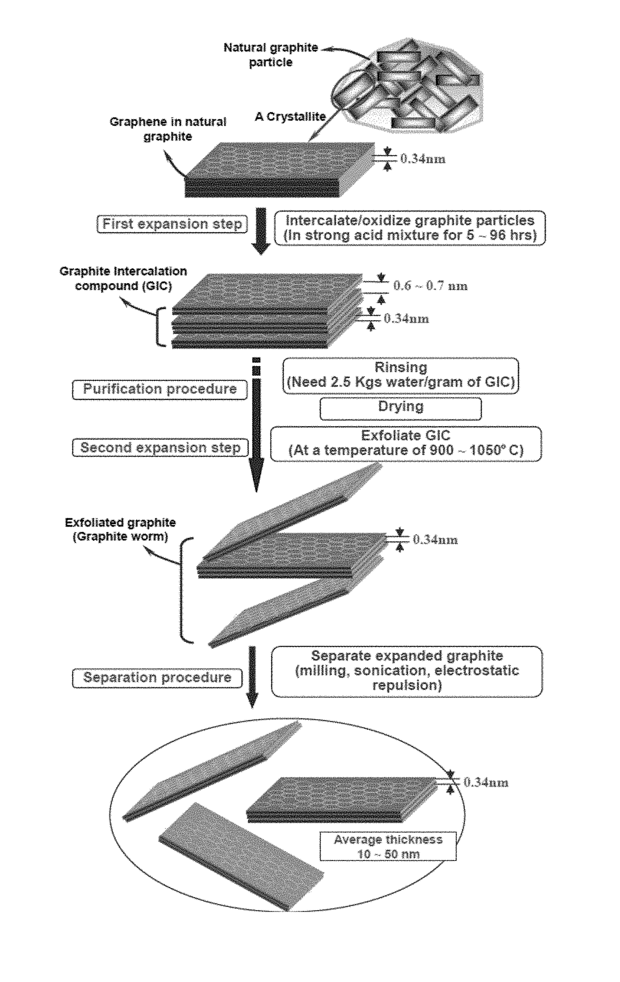
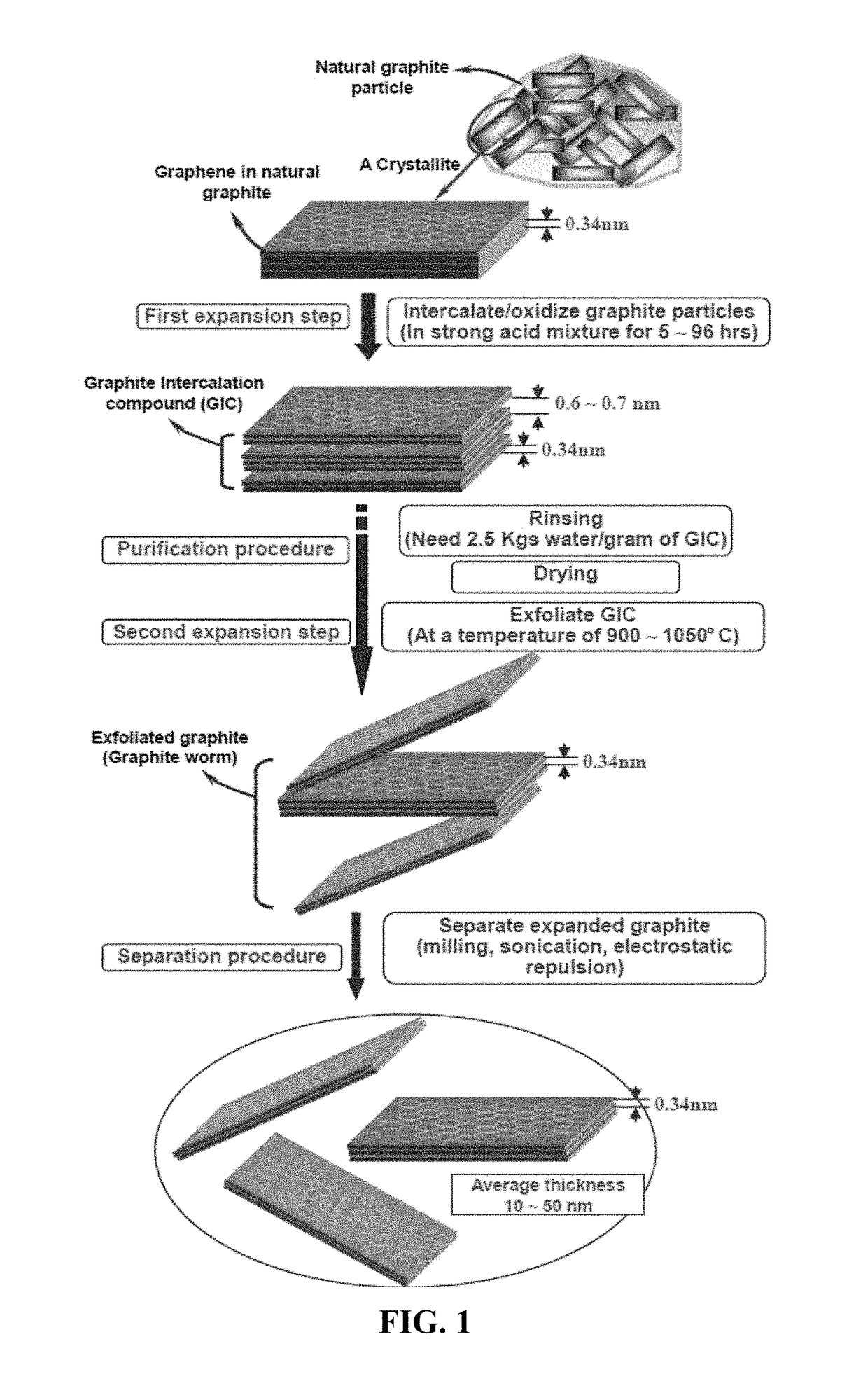
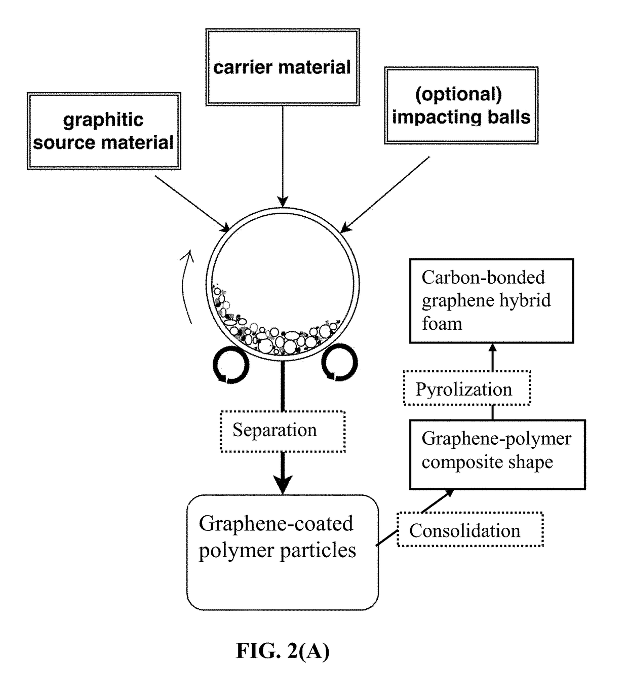
Production of Graphene-Carbon Hybrid Foam from Flake Graphite Via Polypropylene Powder-Based Solid Polymer Carrier Particles

[0155]In an experiment, 1 kg of polypropylene (PP) pellets, 50 grams of flake graphite, 50 mesh (average particle size 0.18 mm; Asbury Carbons, Asbury N.J.) and 250 grams of magnetic stainless steel balls were placed in a high-energy ball mill container. The ball mill was operated at 300 rpm for 2 hours. The container lid was removed and stainless steel balls were removed via a magnet. The polymer carrier material was found to be coated with a dark graphene layer. Carrier material was placed over a 50 mesh sieve and a small amount of unprocessed flake graphite was removed.

[0156]A sample of the coated carrier material was then immersed in tetrachloroethylene at 80° C. for 24 hours to dissolve PP and allow graphene sheets to disperse in the organic solvent for the purpose of determining the nature of graphene sheets produced. After solvent removal, isolated graph...

example 2

Graphene-Carbon Hybrid Foam Using Expanded Graphite (>100 nm in Thickness) as the Graphene Source and Acrylonitrile-Butadiene-Styrene Copolymer (ABS) as the Polymer Solid Carrier Particles

[0163]In an experiment, 100 grams of ABS pellets, as solid carrier material particles, were placed in a 16 oz plastic container along with 5 grams of expanded graphite. This container was placed in an acoustic mixing unit (Resodyn Acoustic mixer) and processed for 30 minutes. After processing, particles of the carrier material were found to be coated with a thin layer of carbon. A small sample of carrier material was placed in acetone and subjected to ultrasound energy to speed dissolution of the ABS. The solution was filtered using an appropriate filter and washed four times with additional acetone. Subsequent to washing, filtrate was dried in a vacuum oven set at 60° C. for 2 hours. This sample was examined by optical microscopy and Raman spectroscopy, and found to be graphene. The remaining pell...

example 3

Production of Graphene-Carbon Hybrid Foam from Meso-Carbon Micro Beads (Mcmbs) as the Graphene Source Material)) and Polyacrylonitrile (PAN) Fibers (as Solid Carrier Particles)

[0164]In one example, 100 grams of PAN fiber segments (2 mm long as the carrier particles), 5 grams of MCMBs (China Steel Chemical Co., Taiwan), and 50 grams of zirconia beads were placed in a vibratory ball mill and processed for 2 hours. After the process was completed, the vibratory mill was then opened and the carrier material was found to be coated with a dark coating of graphene sheets. The zirconia particles, having distinctly different sizes and colors were manually removed. The graphene-coated PAN fibers were then compacted and melted together to form several composite films. The films were subjected to a heat treatment at 250° C. for 1 hour (in room air), 350° C. for 2 hours, and 1,000° C. for 2 hours (under an argon gas atmosphere) to obtain graphene-carbon foam layers. Half of the carbonized foam l...


PUM


Abstract

Provided is a lithium or sodium metal battery having an anode, a cathode, and a porous separator and/or an electrolyte, wherein the anode contains an integral 3D graphene-carbon hybrid foam composed of multiple pores, pore walls, and a lithium-attracting metal residing in the pores; wherein the metal is selected from Au, Ag, Mg, Zn, Ti, Na, K, Al, Fe, Mn, Co, Ni, Sn, V, Cr, or an alloy thereof and is in an amount of 0.1% to 50% of the total hybrid foam weight or volume, and the pore walls contain single-layer or few-layer graphene sheets chemically bonded by a carbon material having a carbon material-to-graphene weight ratio from 1/200 to 1/2, wherein graphene sheets contain a pristine graphene or non-pristine graphene selected from graphene oxide, reduced graphene oxide, graphene fluoride, graphene chloride, graphene bromide, graphene iodide, hydrogenated graphene, nitrogenated graphene, doped graphene, chemically functionalized graphene, or a combination thereof.

Description

FIELD OF THE INVENTION[0001]The present invention relates generally to the field of alkali metal battery (e.g. lithium metal battery or sodium metal battery) and, more particularly, to a lithium or sodium metal secondary battery having an integral 3D graphene-carbon-metal hybrid foam-based electrode and a process for producing this electrode and battery.BACKGROUND OF THE INVENTIONA Critical Review on Alkali Metal Secondary Batteries[0002]Rechargeable lithium-ion (Li-ion) and lithium metal batteries (e.g. Li-sulfur, Li metal-air, and lithium-metal oxide batteries) are considered promising power sources for electric vehicle (EV), hybrid electric vehicle (HEV), and portable electronic devices, such as lap-top computers and mobile phones. Lithium as a metal element has the highest capacity (3,861 mAh / g) compared to any other metal. Hence, in general, Li metal batteries have a significantly higher energy density than lithium ion batteries. Similarly, Na metal batteries have a higher ener...

Claims


Application Information

Patent Timeline
IPC IPC(8): H01M4/133H01M4/04H01M4/1393H01M10/054H01M10/0525H01M4/62H01M4/587H01M4/66H01M10/42H01M4/02
CPCH01M4/133H01M2220/20H01M4/043H01M4/045H01M4/0471H01M10/0525H01M10/054H01M4/587H01M4/623H01M4/625H01M4/661H01M10/4235H01M2004/027H01M2004/021H01M2004/028H01M4/1393C01B32/05C01B32/184Y02E60/10C01B32/194C01B32/19H01M4/134H01M4/38H01M4/382H01M4/40H01M4/405H01M4/663H01M4/666H01M4/667H01M4/808H01M10/052H01M12/08Y02T10/70
Inventor ZHAMU, ARUNAJANG, BOR Z.
Owner GLOBAL GRAPHENE GRP INC
Why Eureka
Try Eureka