Twin-wire arc deposited electrode, solid electrolyte membrane, membrane electrode assembly and fuel cell

a technology of membrane electrodes and deposited electrodes, which is applied in the direction of cell components, electrochemical generators, cell component details, etc., can solve the problems of relatively high cost of fabricating electrodes, and high cost of current pem fuel cells. , to achieve the effect of convenient operation

Inactive Publication Date: 2005-05-19
JANG BOR Z +2
View PDF9 Cites 28 Cited by
  • Summary
  • Abstract
  • Description
  • Claims
  • Application Information

AI Technical Summary

Benefits of technology

[0024] 4. The system needed to carry out the invented method is simple and easy to operate. It does not require the utilization of heavy and expensive equipment such as a laser or vacuum-sputtering unit. This feature also makes it possible to undergo roll-to-roll productions, which are fast and continues. In contrast, it is difficult for a method that involves a high vacuum to be a continuous process. The over-all product costs produced by the presently invented vacuum-free method are very low.

Problems solved by technology

However, the current PEM fuel cells are very expensive in terms of cost per kilowatt of power delivered and, hence, their practical application has been limited to specialized applications that can justify their relatively high costs, e.g., in aerospace applications.
A major factor in determining the cost of a PEM fuel cell is the cost of the electrodes, which is, in turn, determined by a number of factors, including primarily (1) the high cost of the precious metal catalysts, which are needed for practical efficiency and (2) the cost of fabricating the electrodes, which typically involves a batch process.
In addition, the cost of a fuel cell system is also indirectly affected by the electrochemical performance of the electrodes which determines the power density of the fuel cell, i.e., the power produced per unit area (e.g., kilowatts per square centimeter).
Although a reduced amount of the costly platinum catalyst is used in these electrodes, the power density obtained using such electrodes has remained unsatisfactory.
Consequently, the cost of such a fuel cell system is still too high.
The relatively poor performance, i.e., low power density, is believed to be due to an ineffective utilization of the catalyst because a substantial fraction of the platinum is not accessible to the reagents.
However, such improved mass activity does not compensate for the low catalyst loading provided by the process of Vilambi-Reddy, et al.
Furthermore, the process of Vilambi-Reddy, et al. is tedious and expensive.
As a consequence, the power density of such electrodes is still insufficient to permit the wide use of PEM fuel cells as sources of electric power.
Other attempts to reduce the costs of PEM fuel cells and to improve their performance have not been very successful.
But, due to the thick film (10 μm) and large platinum particles used, the catalyst efficiency has been less than satisfactory.
The dispersion of catalyst and carbon particles in such an assembly prepared by slurry layer pressing is not uniform, resulting in a reduced utilization efficiency of catalyst particles.
Such a configuration does not make efficient utilization of the catalyst particles.
Furthermore, most of the prior art methods for MEA preparation produce only relatively thick MEA structures and, therefore, are not conducive to the fabrication of thin-film, integrated fuel cells.
Most of the methods used are slow and / or batch processes that are expensive.
For instance, the method for the electro-deposition of catalytic metals using pulsed electric fields is slow, tedious, and costly (e.g., as disclosed in U.S. Pat. No. 6,080,504 issued to E. Taylor on Jun. 27, 2000).
(U.S. Pat. No. 6,171,721, 01 / 09 / 2001), requires expensive high-vacuum equipment, which also limits the preparation to be a batch process, not amenable for continuous, mass production.

Method used


Image

  • Twin-wire arc deposited electrode, solid electrolyte membrane, membrane electrode assembly and fuel cell
  • Twin-wire arc deposited electrode, solid electrolyte membrane, membrane electrode assembly and fuel cell
  • Twin-wire arc deposited electrode, solid electrolyte membrane, membrane electrode assembly and fuel cell

Examples


example 1

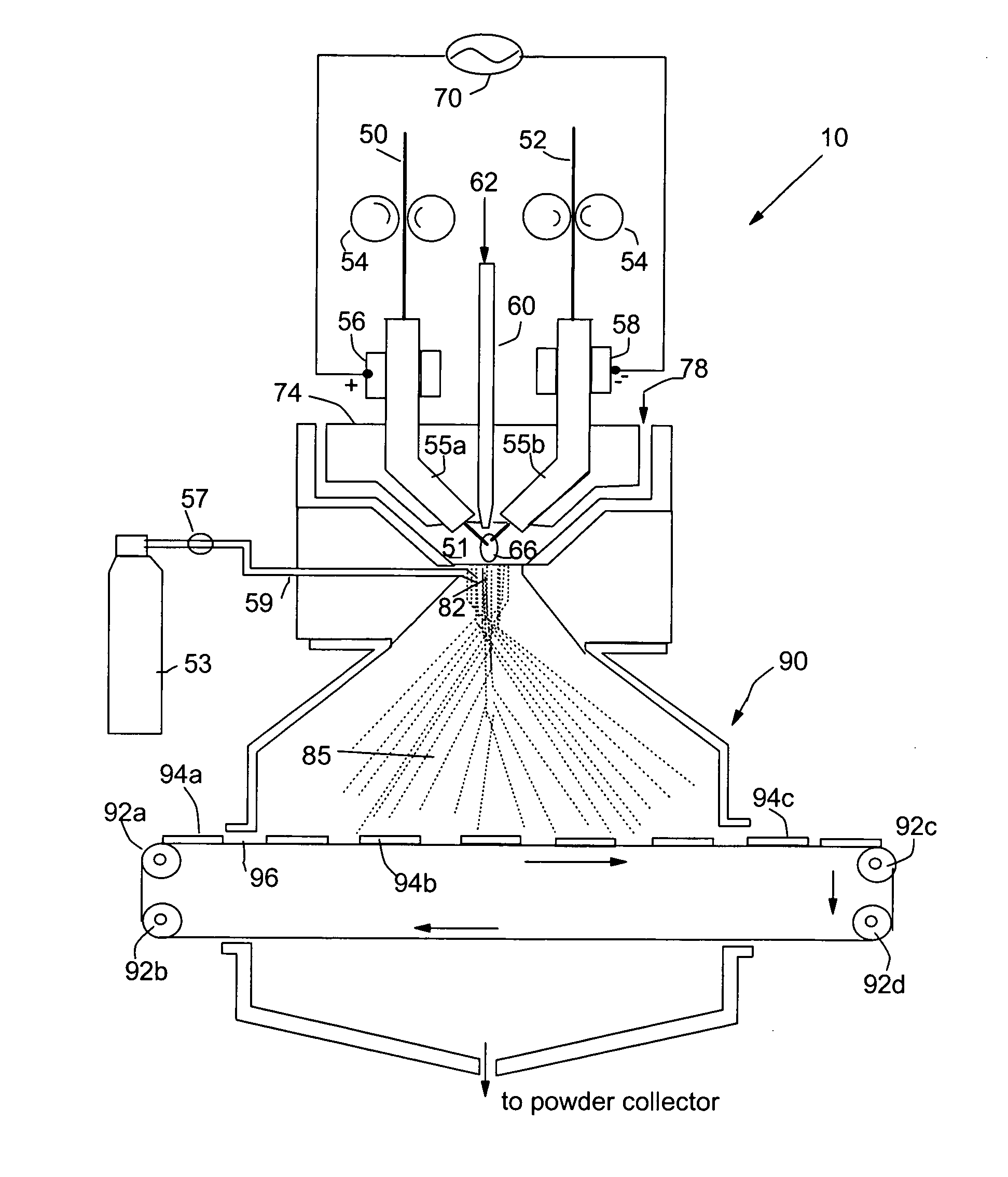
[0074] Metal rods of Cu, Fe, Ti, Ni, Pt and Au each of {fraction (1 / 8)} inches diameter were used as a precursor catalyst material. This arc electrodes were shielded by 25-100 cfh of a working gas of argon combined with 5-100% nitrogen and / or 5-50% hydrogen. The current of the arc was adjusted between approximately 100 and 450 amps, which generated an arc tail flame 1-4 inches long that evaporated the precursor catalyst material. The arc created a stream of metal vapor clusters of 1-200 g / hr while an argon flow of 10-1000 cfh was injected into the tail flame to carry the metal vapor clusters toward a non-woven carbon fiber layer (as a porous air-permeable fuel cell anode). The micro-structure of the resulting catalyst layer was typically characterized by exhibiting catalyst particle sizes in the range of 1-20 nm.

example 2

[0075] Metal rods of Ru-coated Cu, Fe, Ti, and Ni each of {fraction (1 / 8)} inches diameter were used as a precursor catalyst material. This arc cathode was shielded by 25-100 cfh of a working gas of argon combined with 5-100% nitrogen and / or 5-50% hydrogen. The current of the arc was adjusted between approximately 100 and 450 amps, which generated an arc tail flame 1-4 inches long that evaporated the precursor catalyst material. The arc created a stream of metal vapor clusters of 1-200 g / hr while an oxygen flow of 10-1000 cfh was injected into the tail flame to form oxide clusters of the starting metal. These oxide clusters were directed to deposit onto a porous copper plate to form a catalytic oxide layer therein. The micro-structure of the resulting catalyst coatings was typically characterized by particle sizes in the range of 1-15 nm. These transition metal oxide nano particles are effective fuel cell cathode catalysts.

example 3

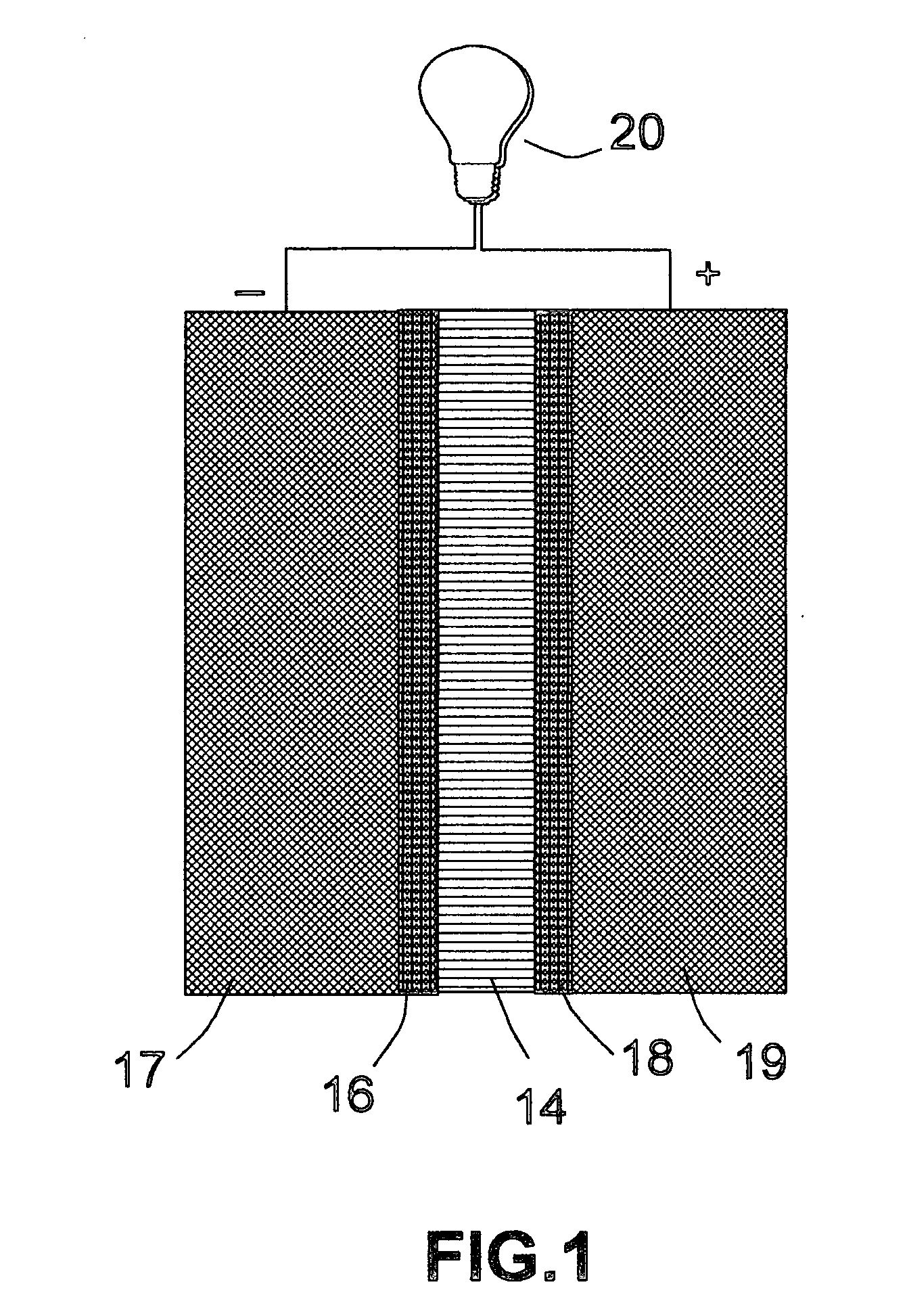
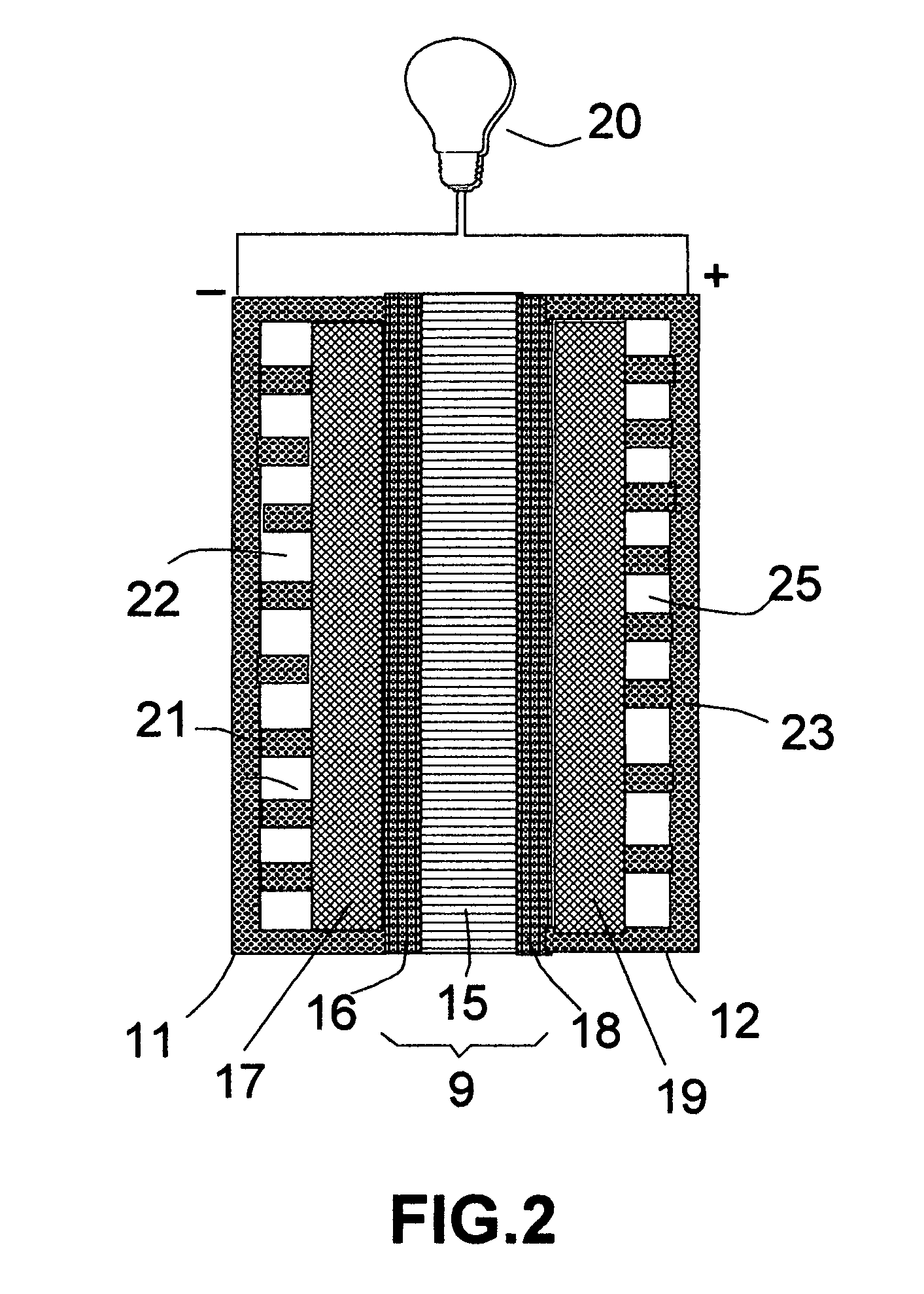
[0076] The same precursor catalyst metals and same deposition procedures as in EXAMPLE 2 were used to deposit an oxide based catalyst layer onto two major surfaces of a solid oxide electrolyte, which was yttrium oxide stabilized zirconium oxide (YSZ). This solid electrolyte layer was sandwiched between two porous electrodes that were composed of a mixture of YSZ and nickel metal to make a membrane-electrode assembly for a solid oxide fuel cell.


PUM

PropertyMeasurementUnit
weightaaaaaaaaaa
weightaaaaaaaaaa
particle sizeaaaaaaaaaa

Abstract

A twin-wire arc deposition method for depositing a nano-structured catalyst coating onto a solid electrolyte membrane or an electrode substrate from a precursor catalyst material selected from the group consisting of a metal, metal alloy, metal compound, and ceramic material. The method includes the steps of (a) providing an ionized arc nozzle comprising two consumable electrode and a working gas flow to form an ionized arc between the two electrodes, wherein the consumable electrodes provide the precursor catalyst material vaporizable therefrom by the ionized arc; (b) operating the arc nozzle to heat and at least partially vaporize the precursor catalyst material for providing a stream of nanometer-sized vapor clusters of the precursor catalyst material into a chamber in which the membrane or the electrode substrate has been placed; and (c) introducing a stream of a carrier gas into the chamber to impinge upon the stream of precursor vapor clusters to produce depositable nano clusters which are carried by the carrier gas to deposit onto a first side of the membrane or the electrode substrate for forming the nano-structured catalyst coating. Such a catalyst-coated membrane or electrode can be incorporated as a part of a fuel cell.

Description

[0001] This invention results from a research sponsored by the U.S. NSF SBIR Program. The U.S. government has certain rights on this invention.FIELD OF THE INVENTION [0002] The present invention relates to a gas diffusion electrode, a solid electrolyte membrane, a membrane electrode assembly (MEA), a fuel cell and a method for producing such an electrode, membrane, MEA, and fuel cell. In particular, the invention provides a method that is capable of mass-producing gas diffusion electrodes, solid electrolyte membranes, and membrane-electrode assemblies containing high-utilization, nano-structured catalyst materials for fuel cell applications. BACKGROUND OF THE INVENTION [0003] Several types of fuel cells have been developed to provide efficient sources of electrical power with reduced pollution. A particularly advantageous type is the proton exchange membrane (PEM) fuel cell. A PEM fuel cell typically is composed of, among other components, two gas diffusion electrodes (GDEs) with a ...

Claims


Application Information

Patent Timeline
Patent Type & Authority Applications(United States)
IPC IPC(8): B05D5/12C23C4/12H01M4/86H01M4/88H01M8/00H01M8/10H01M8/12
CPCC23C4/125H01M4/881H01M4/8842H01M4/8867Y02E60/525H01M2008/1095H01M2008/1293H01M2300/0065Y02E60/523H01M8/1213C23C14/228C23C4/131Y02E60/50
Inventor JANG, BOR Z.HUANG, WEN C.WU, LEON
Owner JANG BOR Z
Why Eureka
Try Eureka