Multiphoton curing to provide encapsulated optical elements

a technology of optical elements and curing, which is applied in the direction of photomechanical equipment, instruments, originals for photomechanical treatment, etc., can solve the problems of inability to manufacture mass quantities of optical elements/devices, inability to meet the requirements of optical elements, etc., to achieve stable, reliable optical elements/devices, and induce single and/or multi-photon photopolymerization

Inactive Publication Date: 2005-09-22
3M INNOVATIVE PROPERTIES CO
View PDF96 Cites 34 Cited by
  • Summary
  • Abstract
  • Description
  • Claims
  • Application Information

AI Technical Summary

Benefits of technology

[0051] A significant advantage of the present invention is that the refractive index profile of the element may be controlled through shaping the mode profile of the writing beam. This is useful for mode matching to other elements and optimizing the mode profile in the optical element 26. The refractive index profile may be further controlled through appropriate choice of one or more other factors, such as the Tg of the binder, monomer size (in order to control the diffusion rate), and temperature of the sample during exposure. For instance, because the distance a monomer molecule can diffuse depends to some degree on its probability of reaction with a growing polymer chain, diffusion can be controlled by controlling such factors as the waveguide width; the time, intensity, and intensity distribution of the exposure; the concentration of the photoinitiator system, and the reactivity and functionality of the monomer or monomers. Since diffusion is a function of molecular weight, shape, and size, monomer diffusion can be controlled by controlling the molecular weight, shape, and size of the monomer or monomers. Diffusion can also be controlled by controlling the viscosity of the monomer or monomers, as well as the glass transition point of the binder. Since some of these properties, such as viscosity also vary with temperature, variation of temperature and some other factor at the same time may produce a complex interaction. Other variables are the time between exposure and the blanket irradiation step (described below) and the temperature at which the element is stored during the period between multiphoton curing and blanket irradiation.
[0052]FIG. 3 illustrates the step in which body 20 is blanket irradiated, i.e., nonimagewise irradiated, from source 30 with a fluence of energy 32 of a type for which at least the uncured portions 28, and more preferably at least the substantial entirety of body 20 has an optical cross-section for absorption of such energy sufficient to cause photopolymerization of the blanket irradiated portions of body 20. Blanket irradiation can occur using appropriate energy, of an intensity and type effective to induce single and / or multiphoton photopolymerization. As a consequence of blanket irradiation, the photopolymerizable material in uncured portions 28 are cured and hardened, thus encapsulating at least portions of waveguide 26 in a monolithic polymer matrix. The resultant encapsulating structure helps to protect and stabilize waveguide 26. Significantly, even though blanket irradiation might cause photopolymerization through the entirety of body 20, sufficient index of refraction contrast between waveguide 26 and cured portions 28 to support waveguiding is maintained. Preferably, such contrast is greater than 0.03, more preferably greater than 0.04, most preferably greater than 0.05. As described below, it is believed that the formation of a so-called depletion zone at the boundary of the cured optical element via diffusion of low molecular weight species helps to provide such optical contrast.
[0053] Advantageously, blanket irradiation promotes dimensional and chemical stability of the structure. Continued diffusion over time might change the shape and refractive index profile of the optical element. Additionally, after blanket irradiation, most, if not all, of the polymerizable species in the composition have been polymerized, rendering the composition chemically inert with respect to further irradiation, heating, or chemical reaction involving polymerization or crosslinking, providing stable, reliable optical elements / devices with improved physical properties compared to the same without blanket irradiation. Additionally, there is reduced potential for health hazards due to the absence, or near absence, of unpolymerized polymer precursor in the finished device after blanket irradiation.
[0054] The energy source used for achieving blanket irradiation may be actinic (e.g., radiation having a wavelength in the ultraviolet or visible region of the spectrum), accelerated particles (e.g., electron beam radiation), thermal (e.g., heat or infrared radiation), or the like. Preferably, the energy is actinic radiation or accelerated particles, because such energy provides excellent control over the initiation and rate of curing. Additionally, actinic radiation and accelerated particles can be used for curing at relatively low temperatures. This avoids degrading components that might be sensitive to the relatively high temperatures that might be required to initiate curing of the photopolymerizable groups when using thermal curing techniques. Suitable sources of actinic radiation include mercury lamps, xenon lamps, carbon arc lamps, tungsten filament lamps, lasers, electron beam energy, sunlight, and the like.
[0055]FIG. 4 shows an optional step in which the optically functional, composite structure resulting from the blanket irradiation step and / or imagewise exposure step is heated by heat source 34 to further cure other any thermosetting materials included in the structure. This step is particularly advantageous when the substantially non-diffusing binder component includes nonphotopolymerizable, yet curable thermosetting polymers that undergo crosslinking when heated. Thermally induced curing may optionally occur with or without a suitable catalyst depending upon the nature of the thermosetting material.
[0056] In some embodiments, it can be appreciated that any such thermosetting polymer(s) and the cured photopolymers could form, if desired, entangled, yet substantially separate polymer matrices in which there are substantially no covalent bonds between the two matrices. Such entangled polymer matrices are generally referred to in the art as interpenetrating polymer networks, or IPN's. As another possibility, the materials that form body 20 may include a thermoplastic polymer that does not undergo crosslinking reactions nor covalent bonding with the photopolymerized polymer matrix, yet these may still comprise polymer chains that are entangled within the photopolymerized polymer matrix. Such entangled matrices are generally referred to in the art as semi-interpenetrating polymer networks, or semi-IPN's. The nature of the thermoplastic and / or thermoplastic polymer constituents, if any, as well as other compositional aspects of the photopolymerizable composition incorporated into body 20 will be described in more detail below.

Problems solved by technology

Both approaches are labor intensive and costly.
The cost increases proportionately with the number of fibers used due to the additional labor needed to fuse or attach each individual fiber.
Such intensive labor inhibits mass production of these devices.
A further problem results from the mismatch in shape of the optical modes in the glass fiber and the integrated optical device.
This mismatch tends to cause insertion losses when a fiber is butt coupled to an integrated optical device.
The manufacture of other three dimensional, micro-optical elements has been quite challenging.
However, the range of shapes that can be made using lithography are limited by a number of factors including surface tension effects.
Photolithography also is limited to the fabrication of elements whose optical axis is normal to the substrate upon which the element is fabricated.
It is difficult, for instance, to make elements with accurate undercuts using photolithography.
Alignment of the layers during assembly to form the laminate structure could also prove problematic.
The layers would also be subject to delamination if the bond quality between layers is poor.
Also, because multiphoton processes involve the simultaneous absorption of two or more photons, the adsorbing chromophore is excited with a number of photons whose total energy equals the energy of an excited state of the chromophore, even though each photon individually has insufficient energy to excite the chromophore.
Elements made to date have not been made in fully cured materials, thus, having poor stability, especially when exposed to light.
Others are free standing and are not encapsulated, thus being sensitive to the surrounding environment and having potential stability issues relative to optical performance.
It is also more challenging to achieve high circuit density when the boundaries between adjacent elements cannot be controlled with sufficient precision.

Method used


Image

  • Multiphoton curing to provide encapsulated optical elements
  • Multiphoton curing to provide encapsulated optical elements
  • Multiphoton curing to provide encapsulated optical elements

Examples


example 1

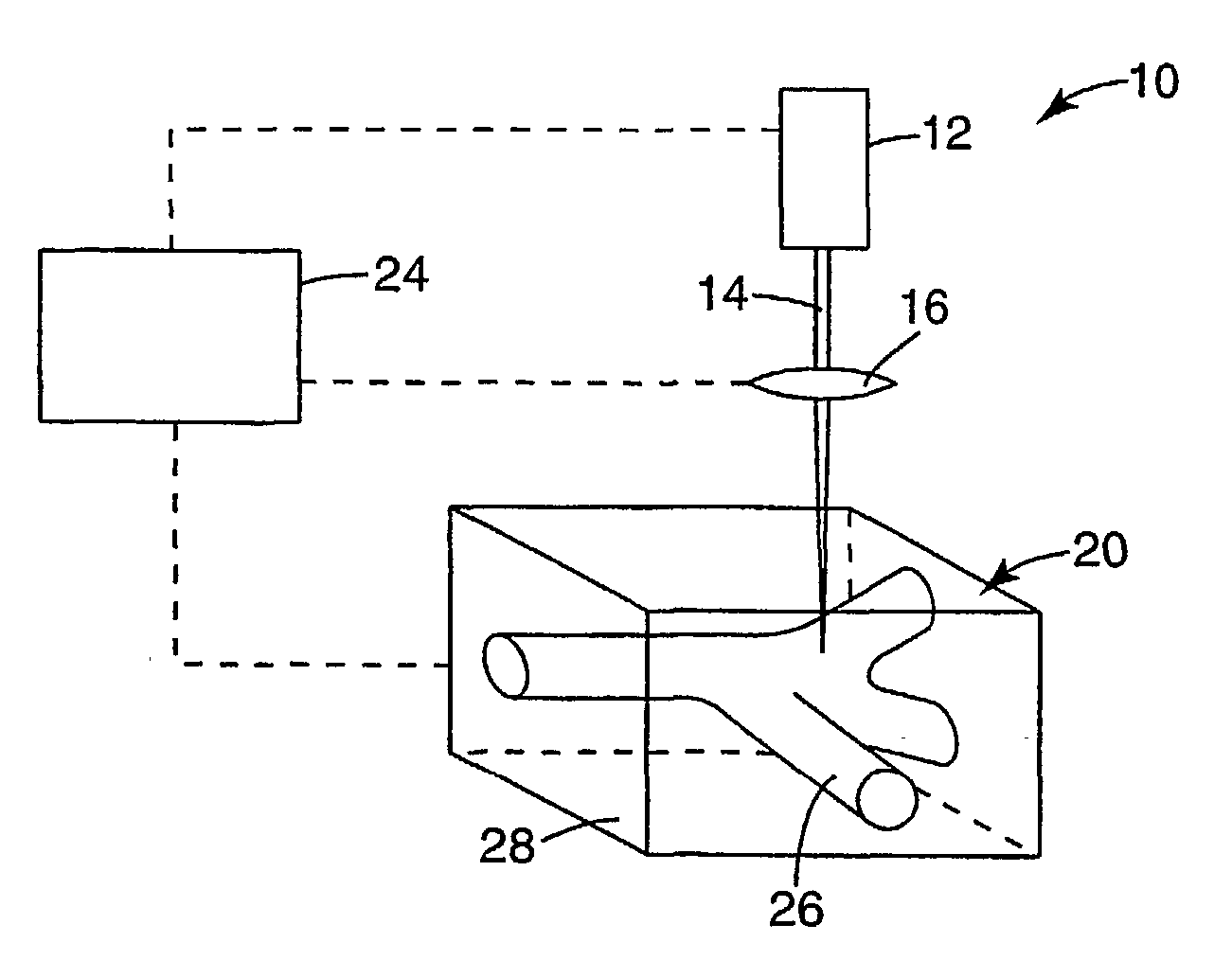
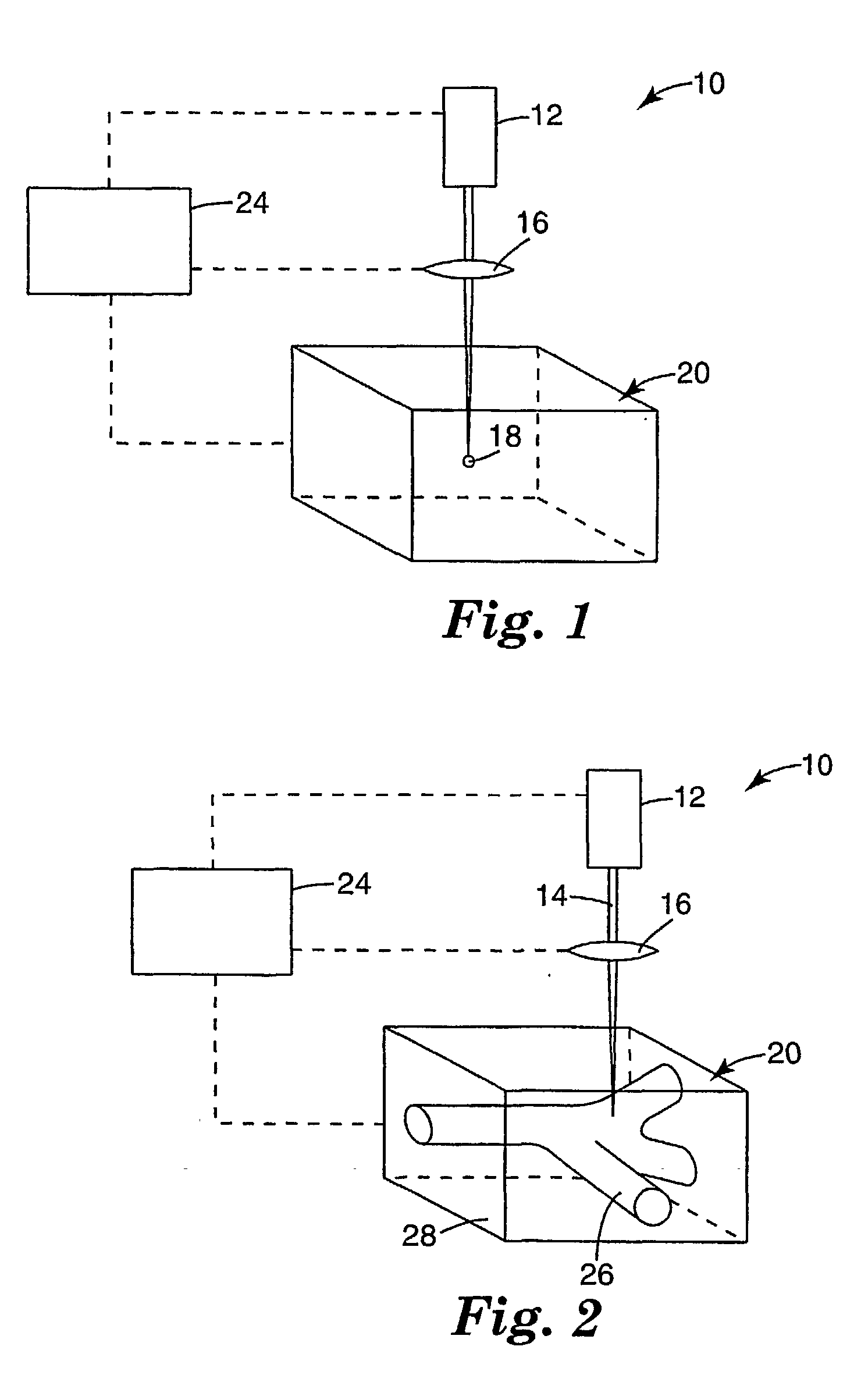
[0107] A solution (40% solids in methylene chloride) containing 40% by weight polymethyl methacrylate (mw 120,000, n=1.490, Aldrich Chemical Co., Milwaukee, Wis.), 25% by weight phenoxyethyl acrylate, 34% by weight of bisphenol A glycerolate diacrylate (Ebecryl 3700™, UCB Chemicals, Symrna, Ga.), and 1% by weight 4,4′-bis(diphenylamino)-trans-stilbene is prepared. The solution is coated on a silicon wafer approximately 500 microns thick and dried in an oven at 60° C. Exposure is performed using a two-photon microscope with a Ti:Sapphire laser operating the two-photon absorption maximum of 4,4′-bis(diphenylamino)-trans-stilbene, 700 nm, and the light is focused through an oil-immersion objective with NA=1.4. X-Y-Z control of the sample is accomplished using a manipulator mounted on the microscope stage. A pattern of interconnected waveguides with primary axes parallel and perpendicular to the plane of the film is written into the medium, resulting in a three dimensional image of the ...

example 2

[0108] A solution (40% solids in methylene chloride) containing 60% by weight cellulose acetate butyrate (MW 70,000, 13.5 wt % acetyl, 37 wt % butyryl, Aldrich Chemical Co., Milwaukee, Wis.), 25% by weight phenoxyethyl acrylate (Aldrich Chemical Co.), 34% by weight bisphenol A glycerolate diacrylate (Ebecryl 3700™, UCB Chemicals), and 1% by weight 4,4′-bis(diphenylamino)-trans-stilbene is prepared. The solution is coated on a silicon wafer approximately 500 microns thick and dried in an oven at 60° C. Exposure is performed using a two-photon microscope with a Ti:Sapphire laser operating at the two-photon absorption maximum of 4,4′-bis(diphenylamino)-trans-stilbene, 700 nm, and the light is focused through an oil-immersion objective with NA=1.4. X-Y-Z control of the sample is accomplished using a manipulator mounted on the microscope stage. A pattern of interconnected waveguides with primary axes parallel and perpendicular to the plane of the film is written into the medium, resultin...

example 3

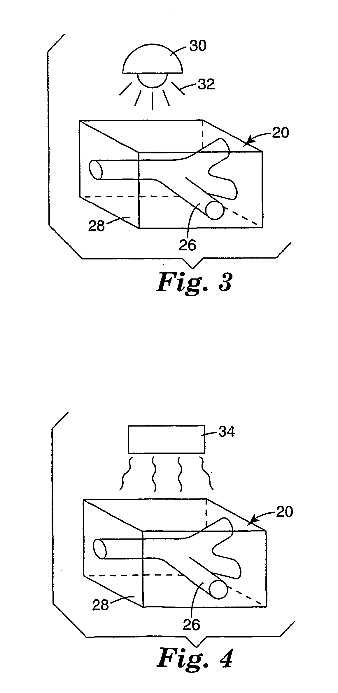
[0116] A low refractive index buffer layer between glass and active layers was prepared by spin coating a solution of the composition given in Table 1 (16% solids in 1,2-dichloroethane) onto microscope slides, evaporating the solvent in an 80° C. oven for 10 minutes, and then curing for 10 minutes under Sylvania 350BLB UV lights. The cured buffer layer thickness was approximately 10 microns thick.

TABLE 1Composition of the buffer layerIngredientWeight %Cellulose acetate butyrate (Eastman Chemicals,89.37Kingsport, TN)Trimethylpropane triacrylate, SR-351 (Sartomer Co.8.94West Chester, PA)Benzil dimethyl ketal, Esacure KB1 (Sartomer Co.1.70West Chester, PA)

[0117] The active layer, the composition of which is given in Table 2, was then spun coat from 25% solids solution in 1,2-dichloroethane on top of the prepared buffer layer and dried in an 80° C. oven for 10 minutes. To further increase the thickness, a second active layer was spun on top and the samples dried again. The final thick...


PUM

PropertyMeasurementUnit
wavelengthsaaaaaaaaaa
weight percentaaaaaaaaaa

Abstract

Methods of fabricating optical elements that are encapsulated in monolithic matrices. The present invention is based, at least in one aspect, upon the concept of using multiphoton, multi-step photocuring to fabricate encapsulated optical element(s) within a body of a photopolymerizable composition. Imagewise, multi-photon polymerization techniques are used to form the optical element. The body surrounding the optical element is also photohardened by blanket irradiation and/or thermal curing to help form an encapsulating structure. In addition, the composition also incorporates one or more other, non-diffusing binder components that may be thermosetting or thermoplastic. The end result is an encapsulated structure with good hardness, durability, dimensional stability, resilience, and toughness.

Description

STATEMENT OF PRIORITY [0001] This application claims the priority of U.S. Provisional Application No. 60 / 211,709 filed Jun. 15, 2000, the entire contents of which are hereby incorporated by reference.FIELD OF THE INVENTION [0002] This invention relates to the use of multiphoton-induced photopolymerization methods for fabricating optically functional elements (e.g., waveguides, diffraction gratings, splitters, couplers, lenses, ring resonators, other optical circuitry, and the like, etc.) that find particular utility in optical communication systems. BACKGROUND OF THE INVENTION [0003] Optical interconnects and integrated circuits may be used, in one application, to optically connect one or more optical fibers to one or more remote sites, typically other optical fibers. For example, where light is carried by one or more input fiber(s), the light may be transferred to, split between, or merged into one or more remote sites. Active or passive devices within the optical integrated circui...

Claims


Application Information

Patent Timeline
Patent Type & Authority Applications(United States)
IPC IPC(8): B29C67/00B29L11/00C08F291/00G02B1/04G02B3/00G02B6/12G02B6/122G02B6/13G02B6/138G03F7/00G03F7/031G03F7/20
CPCG02B6/1221G02B6/13G02B6/138G02B2006/121G02B2006/12102G02B2006/12107Y10S430/146G02B2006/1215G03F7/0005G03F7/031G03F7/2053G03H2001/0484G02B2006/12147B33Y80/00G02B6/30Y10T428/31667G02B6/00G02B6/10G03C5/00
Inventor DEVOE, ROBERT J.LEATHERDALE, CATHERINE A.FLEMING, PATRICK R.POTTS, JOHN E.FLORCZAK, JEFFREY M.
Owner 3M INNOVATIVE PROPERTIES CO
Why Eureka
Try Eureka