Production of iron using environmentally-benign renewable or recycled reducing agents

a technology of reducing agent and renewable or recycled reducing agent, which is applied in the direction of furnace details, furnaces, furnaces, etc., can solve the problems of increasing the level of carbon dioxide in the atmosphere and environmental problems, and achieve the effects of reducing the melting point, convenient shipping, and stable against corrosion

Active Publication Date: 2007-09-13
MICHIGAN TECHNOLOGICAL UNIVERSITY
View PDF30 Cites 24 Cited by
  • Summary
  • Abstract
  • Description
  • Claims
  • Application Information

AI Technical Summary

Benefits of technology

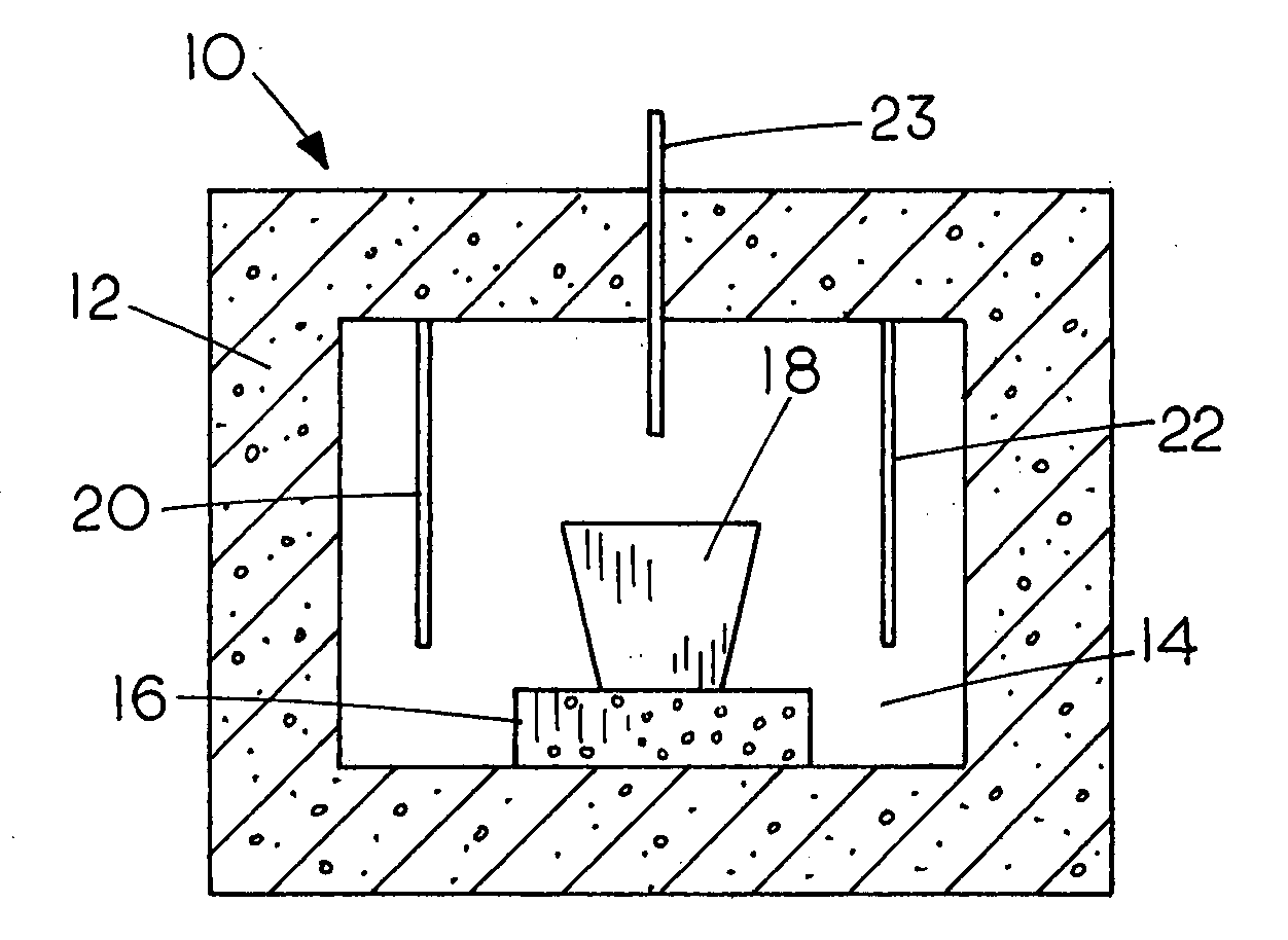
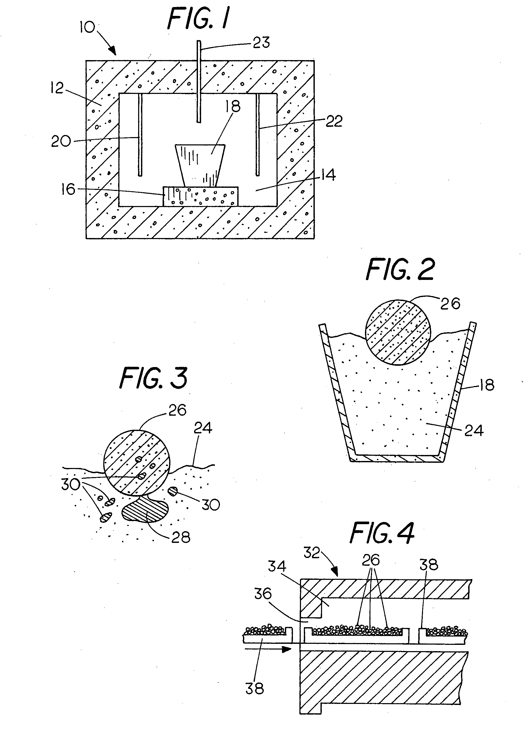
[0040]The size of the iron nuggets 28 and 30 produced is controlled by supporting the pellets on a refractory bed preferably composed of particles that will not be wetted by the molten metal so that the droplets are distinct from the refractory supporting medium and can be separated from it. FIG. 3 shows the iron nuggets after smelting. It was found that the size of the iron pieces that are produced is controlled by supporting the coherent mass of ore and reductant 26 on a bed of refractory particles 24 especially fine particles that will not be wetted by the molten metal 28 and 30. As the pellets 26 or other bodies are converted to metallic iron nuggets 28 and 30, the liquid iron melts and flows to collect in pockets in the refractory bed under the pellets. Some of these drops of liquid iron merge, but for the most part, they remain as separate drops 28 and 30 that form individual metal bodies or nuggets upon cooling. Various refractory materials can be used. Examples of suitable refractories include alumina (Al2O3) mixed with boron nitride or mullite (Sillimanite) (2SiO2:3Al2O3) mixed with zirconia (ZiO2). Another suitable refractory that can be used is powered graphite or carbon particles such as petroleum coke. In producing sample quantities of metallic iron as in the figures, a refractory comprising bed of ground petroleum coke which largely fills the crucible can be used. The refractory material is not consumed but only serves to support the agglomerates as they melt to form free metallic iron while the pellets 26 or other agglomerates of ore and biomass material rest on the loose bed of refractory material 24.
[0041]Refer now to FIG. 4 which illustrates diagrammatically a smelting operation in accordance with the invention in an industrial smelting furnace that is used on a commercial scale for smelting iron. In this case a conveyorized furnace is shown by way of example. The invention can however be applied in a variety of furnaces including rotary hearth furnaces, shaft furnaces or bath smelting furnaces among others. The furnace indicated generally by the numeral 32 is formed largely from a refractory material and includes a furnace chamber 34 having an inlet 36 and a conveyorized transporter only a part of which is shown including ore carriers 38 that pass into the furnace 32 during operation through the inlet 36 into the heated furnace interior 34. The carriers 38 are filled as they enter the furnace with a layer of the preformed bodies 26 containing the ore and reductant as described above which can be piled up to any desired depth or placed in a single layer equal to the height of only one of the bodies 26 so that each one of the agglomerates 26 supported on the upwardly facing refractory surface of the carrier 38 which may be either a solid refractory or comprise loose particles of any suitable commercially available refractory in powered form. After the smelting operation is completed in the furnace 32, the carriers 38 are unloaded and the metallic iron is separated from the remaining slag. The resulting iron pieces or nuggets are conveniently shipped, are stable against corrosion and can be used as a replacement for scrap iron in basic oxygen furnaces or for remelting in electric furnaces used in steel making.
[0042]It has been found that smelting can be carried out at relatively low temperatures using the invention. Iron nuggets have been produced using biomass reductant at temperatures of 1350° C.-1450° C. with processing times of from about 20 to about 40 minutes. The highest furnace temperature that can be used is limited only by the capability of the furnace. It is possible that metallic iron could be made using the invention at a temperature somewhat lower than 1350° C. e.g., 1300° C. by allowing additional time for the carbon contained in the biomass material or synthetic resin to diffuse into the metal and reduce its melting point. In an industrial implementation, any heat source capable of reaching the desired temperature will be suitable as previously noted including electric heating, natural gas, coal combustion or the combustion of any other economical high temperature fuel. The invention is capable of producing outstanding yields. Yields as high as 84.5% have already been achieved which compares very favorably with that of a conventional blast furnace which may yield only 1,000 tons of pig iron for each 2,000 tons of hematite (Fe2O3) for a yield of 71.4%.
[0043]After smelting when the agglomerate has cooled it was found that the porous, low-density slag contained most of the impurities and that it easily broke free from the metallic iron bodies that were produced. While the metallic iron can be produced with only the theoretical stoichiometric amount needed to reduce the iron, for practical purposes and to assure sufficient reductant, in practice a quantity of organic material is used that is in excess of the amount that is theoretically needed to reduce the iron. The iron ore preferably comprises between about 60%-90% by weight of the mass and most preferably from about 65% to about 85% of the mass. Iron nuggets can be successfully produced using the invention with essentially complete reduction of the iron oxides to iron using biomass additions material in the range of about 20%-30% of the oxide by weight of the pellet or other agglomerated mass. Both magnetite (Fe3O4,) and hematite (Fe2O3) have been successfully reduced through the use of the invention to produce metallic iron. The carbon content of the resulting metallic iron was in the range of about 2% to about 4%; a pig iron product which may have an iron content up to about 4% by weight. Pig iron produced by traditional processes averages about 92%-94% iron with the balance made up of carbon and other impurities. The pig iron produced by the present invention is stable against corrosion, can conveniently be shipped and is outstanding feed stock for steel making either by remelting in electric furnaces or by replacement of scrap iron in basic oxygen furnaces.
[0044]On an industrial scale, the present invention makes it possible to produce pig iron nuggets using any of several types of furnaces including rotary hearth furnaces, shaft furnaces or bath smelting furnaces. In addition to electric resistor furnaces, other types of furnaces can be used such as induction heating furnaces in which an alternating magnetic flux is used to produce heating in an electrically conductive substance or by other means such as arc furnaces, among others. As already noted, the heat for carrying out the smelting operation is supplied separately from the material used as a reductant in the conversion process while the reducing power for converting the oxide to free metal is provided by the hydrocarbon or carbohydrate polymer that is part of the coherent mass that makes up the pellet, briquette or other agglomerated body.
[0045]The iron making industry has, prior to the present invention been unable to take advantage of the large quantities of biomass and recycled organics such as recycled synthetic plastic resins in smelting iron ore which the present invention now makes use of.

Problems solved by technology

As a fossil fuel, coal and natural gas is not sustainable in the long term and also leads to increasing levels of carbon dioxide in the atmosphere.
However, besides being a limited nonrenewable resource, the burning of coal has caused environmental problems through the distribution of heavy metals such as mercury into the environment and the production of greenhouse gases which are widely acknowledged to be undesirable.

Method used


Image

  • Production of iron using environmentally-benign renewable or recycled reducing agents
  • Production of iron using environmentally-benign renewable or recycled reducing agents

Examples


example 1

[0050]An iron ore concentrate comprising magnetite (Fe3O4) from the Empire mine, Ishpeming MI, consisting of particles 90% passing 25-micrometer screen and containing 5% silica was mixed with ground wood comprising Carbondry® wood chips averaging about 1 inch in length and ⅛ inches in thickness provided by Carbontec, Energy Corporation of Bismarck N.D. containing about 5% moisture. The chips were dry ground in a rod mill to pass through a 4.75 mm sieve. A small quantity of wheat flour was also added to act as a binder since the ground wood did not have enough cohesion to be formed into a cohesive mass. The magnetite and ground wood and flour were weighed, mixed together in a kneader-mixer with moisture added to produce slight moistening until the mixture began to agglomerate. The mixture was then formed into balls containing about 25 grams of iron ore concentrate and about 7.5 grams of ground wood chips and wheat flour, resulting in a reductant weight that was 30% of the weight of t...

example 2

[0051]Metallic iron was produced from magnetite in four experiments as in Example 1 except that the firing temperature was reduced to 1425° C. and 1400° C. The feed mixture consisted approximately of magnetite 100 grams, ground wood 30 grams and wheat flour 2 grams. The combined mixture was divided into four portions to form agglomerates containing approximately 25 grams of magnetite, 7.5 grams of ground wood, and 0.5 grams of wheat flour each. A good metallic iron product was produced when the firing time was at least 20 minutes.

example 3

[0052]In a third run, the feed mixture consisted of magnetite 100 grams, ground wood 20 grams and wheat flour 2 grams. The combined mixture was divided into four portions to form agglomerates containing approximately 25 grams of magnetite, 5 grams of ground wood, and 0.5 grams of wheat flour each. The individual pellets were then fired at temperatures ranging from 1375° C. to 1425° C. After firing in the furnace, a good metallic iron nugget product was produced.

[0053]The results obtained from Examples 2 and 3 are shown in Table 1 below:

TABLE 1Mixture RatioHeatingInitialFinishedSampleMagnetite;FurnaceTime,Pellet Wt.,Nugget Wt.,Estimated %ExampleNumberWood; FlourTemp., ° C.MinutesGramsGramsiron recovery21100:30:214251531.4(no slag separation)2100:30:214252032.1313.7882.293100:30:214252531.5413.8284.074100:30:214003031.9414.0784.5235100:20:214252530.2713.8781.266100:20:214252029.6511.5669.147100:20:214003029.9513.1477.818100:20:213753029.6313.0878.28

[0054]The column marked “Initial Pel...


PUM

PropertyMeasurementUnit
temperatureaaaaaaaaaa
diameteraaaaaaaaaa
massaaaaaaaaaa

Abstract

To produce metallic iron from iron ore, a composition comprising a mass of material formed from a mixture of iron ore particles and particles of a reductant that is either a biomass material in particulate form or a plastic resinous material in particulate form is used. The reductant can also be a mixture of biomass material and resin in any proportions. The mass of material comprises at least one body having a shape adapted for smelting such as pellets, briquettes, pieces or lumps. The pellets have sufficient cohesion to maintain the shape into which they have been formed. The invention also provides a new method for smelting iron from its ore which comprises subdividing the ore into particles of a selected size, mixing the subdivided ore particles with particles of a biomass material or particles of a plastic resinous material or with mixtures thereof, forming a mass of the mixture into at least one body with a shape that is suited for smelting in a furnace and placing the body in a furnace and exposing it to sufficient heat to bring the iron therein to smelting temperature within the furnace to thereby produce metallic iron directly from the ore.

Description

[0001]This application claims the benefit of provisional application Ser. No. 60 / 781,796 bearing the same title and filed Mar. 13, 2006 which is incorporated herein by reference.FIELD OF THE INVENTION[0002]This invention relates to the smelting of ore and more particularly a composition and method for the production of metallic iron from iron ore.BACKGROUND OF THE INVENTION[0003]Since ancient times iron production from iron ore made use of fuels such as coal or charcoal containing free carbon to produce the heat and reducing gases necessary for reduction of the ore. Wood alone produces much less heat, about 6,000-8,000 BTU / lb. compared with coal (12,000-15,000 BTU / lb) and coke (about 12,000-15,000 BTU / lb). In early times with small furnaces and simple air blowing equipment, the temperatures were not high enough to form iron carbide so the iron that formed initially was of little value and the ironmasters had to wait until the fire burned out to retrieve the “bloom,” a mass of 25-50 ...

Claims


Application Information

Patent Timeline
Patent Type & Authority Applications(United States)
IPC IPC(8): C21C7/04
CPCC21B13/0006C21B13/0066C21B13/008C22B5/10C21C2007/0031C22B1/244C22B1/245C21B13/04Y02P10/134Y02P10/20C21B13/00C21C7/04
Inventor EISELE, TIMOTHY C.KAWATRA, SURENDRA KOMAR
Owner MICHIGAN TECHNOLOGICAL UNIVERSITY
Why Eureka
Try Eureka