Process and device for desulphurization and denitration of flue gas

a technology of desulfurization and denitration, which is applied in the direction of dispersed particle separation, separation processes, energy input, etc., can solve the problems of less than 80%, low desulfurization efficiency, and serious environmental pollution, so as to increase the circulation volume and increase the circulation volume of heat storage fluid.

Active Publication Date: 2017-07-13
WEI XIONGHUI +1
View PDF0 Cites 36 Cited by
  • Summary
  • Abstract
  • Description
  • Claims
  • Application Information

AI Technical Summary

Benefits of technology

[0042]Further, the said afterheat recovery tower may be provided with one or more stages of afterheat recovery internal circulation pumps to increase the circulation volume of the heat storage fluid. The absorption tower may also be provided with one or more stages of desulfurization-denitration internal circulation pumps to increase the circulation volume of the desulfurization-denitration solution.

Problems solved by technology

At the same time, sulfur dioxide, sulfur trioxide, hydrogen chloride, hydrogen fluoride, nitrogen oxides, harmful organic substances, bacteria, and the like are readily adsorbed on the surface of these particles, thus the content of atmospheric suspended particles (which are generally referred to as PM100, PM10, PM2.5, etc.) is increased significantly, resulting in the phenomenons of haze and atmospheric photochemical reactions, and causing serious environmental pollution.
However, the desulfurization efficiency is not high, usually less than 80%, and the ratio of Ca / S (Mg / S) is far greater than 1.5, which means a large resource consumption of oxide or carbonate containing element of calcium or magnesium.
Dry desulfurizing agent is consumed in a great amount and is expensive, and a lot of waste residues are produced at the same time, which need to be piled up and landfilled, resulting in serious pollution transfer and secondary pollution phenomenon.
However, this process generates a lot of solids of calcium sulfate, as well as some solid wastes such as calcium sulfite and unreacted calcium carbonate.
With large limestone consumption, huge devices of crushing and milling, and high power consumption, the investment is great.
Moreover, solid precipitates, which tend to clog the devices, are produced during the absorption process.
Sewage discharge is large, and secondary pollution is serious.
However, this process generates a lot of solids of calcium sulfate, as well as solid wastes such as calcium sulfite, calcium carbonate, and unreacted calcium hydroxide.
With large lime consumption and huge devices, the investment is great.
Moreover, solid precipitates, which tend to clog the devices, are produced during absorption.
Sewage discharge is large, and secondary pollution is serious.
Besides, a large amount of coals is consumed in the calcination process for the production of calcium oxide, which also cause serious pollution.
However, ammonia has high toxicity, very strong volatility and low boiling point, thus phenomenon of ammonia entrained in the flue gas is serious, resulting in heavy loss of ammonia and secondary pollution caused by atmospheric ammonia.
At the same time, the consumption of ammonia in the ammonia desulfurization process is very large, and ammonia is converted into low-valued ammonium sulfate, thus the cost of desulfurization is high, and crystallization is likely to occur, clogging devices and pipelines.
Moreover, ammonia is highly corrosive, thus the device corrosion is serious, and ammonia production process is one of high energy consumption and high pollution, excessive consumption of ammonia is actually a process of worsening environmental pollution and increasing energy consumption indirectly, therefore the use of ammonia should be minimized.
The process is very complex, with a large investment, a large steam consumption and a high energy consumption.
At the same time, a large amount of natural phosphorite ore consumption is required.
Therefore, the technology and process are not applicable anywhere, they can only be used where natural phosphorite ores are available.
However, the magnesium sulfite solids produced in the process tend to clog the pipelines and devices, and also, magnesium sulfite does not decompose until it is calcined at a temperature above 1235K, thus energy consumption is high, investment is large, and secondary pollution is serious.
The technology and process can only be applied at seaside, because the seawater consumption is particularly large.
The process is good in terms of conception, however, practical tests show that the regeneration rate of sodium (or potassium) bisulfite solution during steam heating is very low, only a very small part of sodium (or potassium) bisulfite can be converted into sodium (or potassium) sulfite, most of sodium (or potassium) bisulfite cannot be decomposed, and steam consumption is large.
Therefore, the process has been unable to be industrialized.
There are large-scale application examples of this method in the United States, Germany, France and Japan, but its steam consumption is large, and energy consumption is high.
The process is good in terms of conception, however, practical tests show that the regeneration rate of sulfite in the organic acid-organic acid salt buffer solution during steam heating is very low, only a very small part of sulfite can be converted into organic acid salt, most of sulfite cannot be decomposed, and steam consumption is large.
Therefore, the process has been unable to be industrialized.
As the solution contains some calcium ions, precipitation may occur during desulfurization, clogging pipelines and devices.
The process consumes a large amount of ammonia, and as the flue gas contains about 4%-9% O2, the reaction of ammonia gas with O2 will produce NOX with consumption of ammonia, and reaction of ammonia is not complete, some ammonia is discharged into atmosphere with the flue gas, increasing the loss of ammonia, and causing secondary pollution.
A large amount of fossil fuels are consumed during ammonia production, generating a large amount of waste gas, waste residue, and waste water.

Method used


Image

  • Process and device for desulphurization and denitration of flue gas
  • Process and device for desulphurization and denitration of flue gas
  • Process and device for desulphurization and denitration of flue gas

Examples


Embodiment Construction

[0054]The flue gas desulfurization-denitration process and device of the present invention will be described below in conjunction with specific embodiments. The embodiments are intended to better illustrate the present invention, and should not be construed as limiting the claims of the present invention.

[0055]The operation methods are as follows:

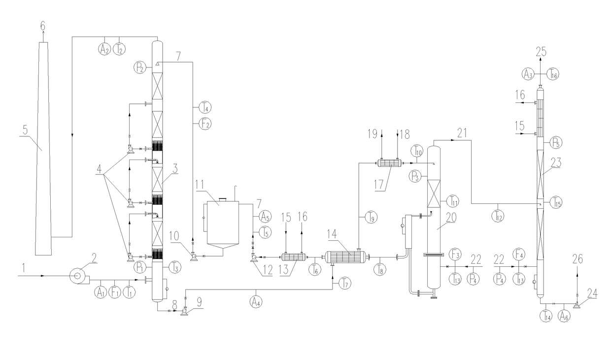
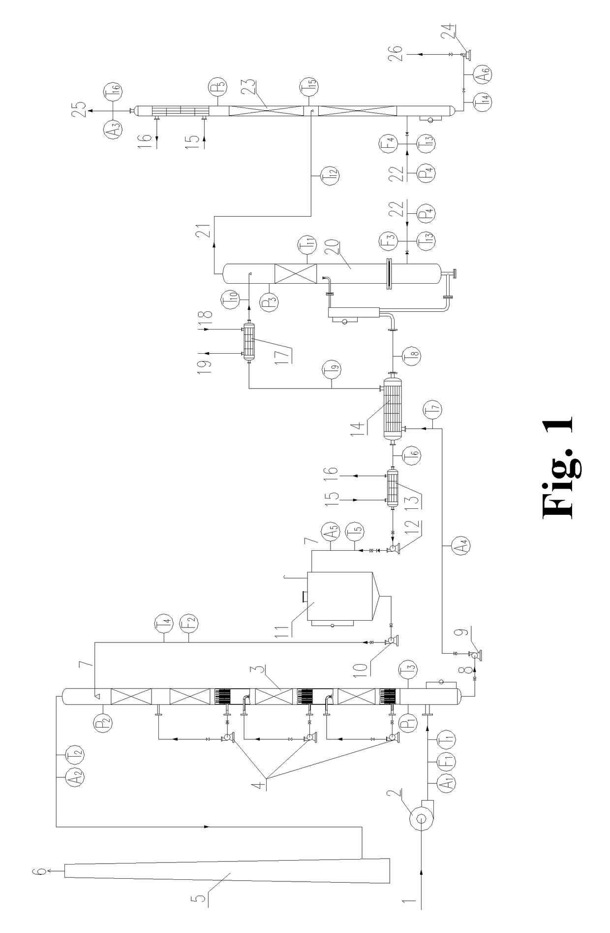
[0056]The operation methods of the processes and devices for the flue gas desulfurization-denitration, the regeneration of the desulfurization-denitration solution and the concentration of sulfur dioxide and / or nitrogen oxides are shown in FIG. 1: A flue gas 1 with a temperature below 50° C. is pressurized by a booster fan 2 and then enters into an absorption tower 3 from the bottom. At the same time, a desulfurization-denitration lean solution 7 enters into the absorption tower 3 from the top. In the absorption tower 3, the flue gas 1 is brought into direct contact with the desulfurization-denitration lean solution 7. At this point, sulfur...


PUM

PropertyMeasurementUnit
temperatureaaaaaaaaaa

Abstract

The invention discloses a process and device for desulfurization-denitration of a flue gas. A desulfurization-denitration solution is used in an absorption tower to absorb sulfur dioxide and/or nitrogen oxides from the flue gas or various combustion tail (waste) gases. The desulfurization-denitration solution with absorbed sulfur dioxide and/or nitrogen oxides releases the sulfur dioxide and/or nitrogen oxides by heating and/or gas stripping and/or vacuum regeneration in a regeneration tower. The released sulfur dioxide and/or nitrogen oxides are further concentrated into a sulfur dioxide and/or nitrogen oxide product with a higher purity in a concentration tower. The regenerated desulfurization-denitration solution is recycled for use. The process and device have a wide range of industrial applications, and can be used for desulfurization and/or denitration of flue gases, incineration gases, coke-oven gases, synthetic waste gases from dyestuff plants, pollutant gases discharged from chemical fiber plants and other industrial raw material gases or waste gases containing SOx.

Description

TECHNICAL FIELD[0001]The present invention relates to the industrial field of gas desulfurization-denitration, and specifically to a process and device for desulfurization-denitration of a flue gas or various combustion tail (waste) gases.BACKGROUND ART[0002]Fossil fuel combustion produces a large amount of flue gases discharged into atmosphere, which, in addition to sulfur dioxide, sulfur trioxide, hydrogen chloride, hydrogen fluoride, nitrogen oxides and a small amount of harmful organic substances, contain a large amount of dusts, there are tiny hydrophilic and non-hydrophilic particles in these dusts (mainly calcium salt particles, aluminum salt particles, magnesium salt particles, titanium salt particles, iron salt particles, lead salt particles, zinc salt particles, cobalt salt particles, rare earth element particles, radioactive element particles and particles of other harmful elements, as well as mineral particles such as silica particles, mullite particles, silicate particl...

Claims


Application Information

Patent Timeline
Patent Type & Authority Applications(United States)
IPC IPC(8): B01D53/96B01D53/78C01B17/60B01D53/18C01B21/20B01D53/60B01D53/14
CPCB01D53/96B01D53/60B01D53/78B01D53/1425B01D53/1481B01D53/1456C01B2210/0007B01D53/18C01B21/20C01B17/60B01D2252/202B01D2257/302B01D2257/404B01D53/1493Y02P20/129
Inventor WEI, XIONGHUI
Owner WEI XIONGHUI
Why Eureka
Try Eureka