Light emitting device with microlens array

a light emitting device and microlens technology, which is applied in the direction of instruments, discharge tubes, luminescnet screens, etc., can solve the problems of limiting the efficiency of oled devices, ineffective capture of most of inability to extract the photons generated by the recombination process, so as to minimize undesirable diffractive effects, enhance the properties of the devices, and improve the diffusion of ambient light

Active Publication Date: 2008-12-18
GLOBAL OLED TECH
View PDF6 Cites 4 Cited by
  • Summary
  • Abstract
  • Description
  • Claims
  • Application Information

AI Technical Summary

Benefits of technology

[0050]The microlens array of the second structured film formed in the method of the present invention can be integrated into a light-emitting device such as a flat-panel pixellated display by adhering the flat side of the second structured film to either a transparent cover or substrate of the light emitting device through which light is emitted. In a preferred embodiment, the light-emitting element is an OLED comprising first and second electrodes and one or more layers of organic light-emitting material formed between the electrodes, wherein at least one electrode comprises a transparent electrode and is positioned between the organic layers and the transparent substrate or cover through which light is emitted.
[0051]The present invention may also be practiced with either active- or passive-matrix light emitting devices. It may also be employed in display devices or in area illumination devices. In a preferred embodiment, the present invention is employed in a flat-panel OLED device composed of small molecule or polymeric OLEDs as disclosed in but not limited to U.S. Pat. No. 4,769,292, issued Sep. 6, 1988 to Tang et al., and U.S. Pat. No. 5,061,569, issued Oct. 29, 1991 to VanSlyke et al. Many combinations and variations of organic light-emitting displays can be used to fabricate such a device, including both active- and passive-matrix OLED displays having either a top- or bottom-emitter architecture. While the invention is described primarily with respect to organic light emitting diode devices, it is not limited to such OLED devices, and may also be employed with other self-emissive light-emitting devices such as inorganic LEDs.
[0052]A typical structure according to a prior art device is shown in FIG. 1. OLED 100 in FIG. 1 includes transparent glass substrate 110.2, anode 110.3, hole-injecting layer (HIL) 120, hole-transporting layer (HTL) 130, exciton-blocking layer (XBL) 140, light-emitting layer (LEL) 150, electron-transporting layer (ETL) 170, electron-injecting layer (EIL) 180 and cathode 190. OLED 200 shown in FIG. 2 is the same as OLED 100, except that there is a microlens array layer 210.1 (microlens array layer 1) disposed on the side of the transparent glass substrate 110.2 opposite to the device side. A structure according to one embodiment of the present invention is shown in FIG. 3. OLED 300 is the same as OLED 100, except that there is a microlens array layer 310.1 (microlens array layer 2) disposed on the side of the transparent glass substrate 110.2 opposite to the device side. The microlens array layer 310.1 is fabricated in accordance with the present invention. OLEDS 100, 200, and 300 can be operated by applying an electric potential produced by a voltage / current source between the pair of the electrodes, anode 110.2 and cathode 190. Light generated inside the devices emits through the transparent glass side. The composition of each organic layer in the OLEDs can be as taught in the prior art.
[0053]The micro-lens array of the present invention provides improved diffusion of ambient light. This is advantageous when concentrated intense light sources such as the sun or incandescent lamps are incident on the display. The specular reflections of such sources detract from the quality of the viewed image. Furthermore, the disordered nature of the micro-lenses in the present invention serves to minimize undesirable diffractive effects from such concentrated intense light sources, which create bright reflected spots or rings that are distracting to the viewer.
[0054]Most OLED devices are sensitive to moisture or oxygen, or both, so they are commonly sealed in an inert atmosphere such as nitrogen or argon, along with a desiccant such as alumina, bauxite, calcium sulfate, clays, silica gel, zeolites, alkaline metal oxides, alkaline earth metal oxides, sulfates, or metal halides and perchlorates. Methods for encapsulation and desiccation include, but are not limited to those described in U.S. Pat. No. 6,226,890 issued May 8, 2001 to Boroson et al. In addition, barrier layers such as SiOx(x>1), Teflon, and alternating inorganic / polymeric layers are known in the art for encapsulation.
[0055]OLED devices can employ various well-known optical effects in order to enhance their properties if desired. This includes optimizing layer thicknesses to yield maximum light transmission, providing dielectric mirror structures, replacing reflective electrodes with light-absorbing electrodes, providing anti-glare or anti-reflection coatings over the display, providing a polarizing medium over the display, or providing colored, neutral density, or color conversion filters over the display. Filters, polarizers, and anti-glare or anti-reflection coatings may be specifically provided over the cover or as part of the cover.

Problems solved by technology

It has been found, however, that one of the key factors that limits the efficiency of OLED devices is the inefficiency in extracting the photons generated by the electron-hole recombination out of the OLED devices.
Due to the high optical indices of the organic materials used, most of the photons generated by the recombination process are actually trapped in the devices due to total internal reflection.
But there are significant problems with this approach.
Also, the micro-lenses do not have the optimum shape.
Although the process is an improvement over the method of Moller and Forrest that is reflected in higher light extraction, a factor of 1.85 versus 1.5; there are still problems to be overcome.
Melting and re-flow of the photo-resist is difficult to control resulting in significant deviations from hemispherical shape.
Furthermore, the distance between lenses is fixed at 1 μm because a smaller spacing or higher resolution is difficult to obtain using this process that is characteristic of “top-down” or conventional micro-fabrication technology.
However, once again the micro-lens array is fabricated by conventional micro-fabrication methods such as wet etching and photo-resist re-flow that have the same disadvantages as noted above.
Furthermore, they do not discuss the effectiveness of the micro-array for light extraction from OLEDs.
Also, fabrication of the array involves a large number of steps that may not be suitable for low-cost high volume manufacturing.
An additional problem with the micro-lens array of Yabu and Shimomura and other micro-lens arrays in the prior art is that the micro-lens array comprises a precisely ordered array of lenses.
An ordered array of lenses in an OLED display can cause significant diffractive artifacts from intense ambient point sources, such as sunlight, or incandescent lamps.
Furthermore, Srinivasarao et al. do not teach how the micro-voided polymer films are to be used for preparing micro-lens arrays for improved light extraction in OLEDs.
Elastomeric materials such as silicones or natural rubber that are hydrophobic and have low surface energy, however, may not have desirable optical properties in terms of refractive index or light transmission or physical properties in terms of scratch resistance.
While it is possible to chemically treat and modify the surface of the first structured film (after it has been prepared and before the second fluid composition is applied on it) to allow materials that are hydrophilic and high surface energy to be released from it, this involves several additional process steps that are not desirable.

Method used


Image

  • Light emitting device with microlens array
  • Light emitting device with microlens array
  • Light emitting device with microlens array

Examples


example 1

Microlens Array

[0057]This example illustrates a method of preparation of a microlens array employed in accordance with an embodiment of the invention.

[0058]A solution containing 20 wt % of a copolymer of bisphenol A polycarbonate (BPAC) and polydimethylsiloxane (PDMS) (49.5 mol % bisphenol A, 50 mol % polycarbonate and 1 mol % PDMS; average molecular weight of 92,000 and 31 repeat units of dimethylsiloxane in each PDMS block) and 0.1% FC431 fluorocarbon surfactant (based on the weight of polymer) in methylene chloride was applied on the vinylidene chloride subbed surface of a sheet of polyethyleneterephthalate (PET) at a wet thickness of 0.25 mm. The wet coating was then immediately inserted into a closed chamber where the temperature and humidity were controlled at 22 C and 65% RH and kept there for 5 minutes. After evaporation of the organic solvent, the sheet was kept in the chamber for an additional 5 minutes and the chamber was purged with nitrogen gas to remove residual water....

example 2

Microlens Array

[0061]This example illustrates preparation of a microlens array employed in a comparative example.

[0062]A solution containing 23.8 wt % polycarbonate (Bayer DPI 1265) and 0.1% FC431 fluorocarbon surfactant (based on the weight of polycarbonate) in dichloromethane was applied on the surface of a sheet of polyethyleneterephthalate (PET) at a coverage of 452 cm3 / m2. The wet coating was then immediately inserted into a closed chamber where the temperature and humidity were controlled at 22 C and 85% RH and kept there for 5 minutes. After evaporation of the organic solvent, the sheet was kept in the chamber for an additional 5 minutes and the chamber was purged with nitrogen gas to remove residual water. The resulting dried polymer film was then peeled off the PET substrate. The film was structured with closely packed hemispherical cavities. Sylgard 184 silicone elastomer base (from Dow Coming Corporation) was combined with Sylgard curing agent (also from Dow Coming) in a ...

example 3

Comparative Device

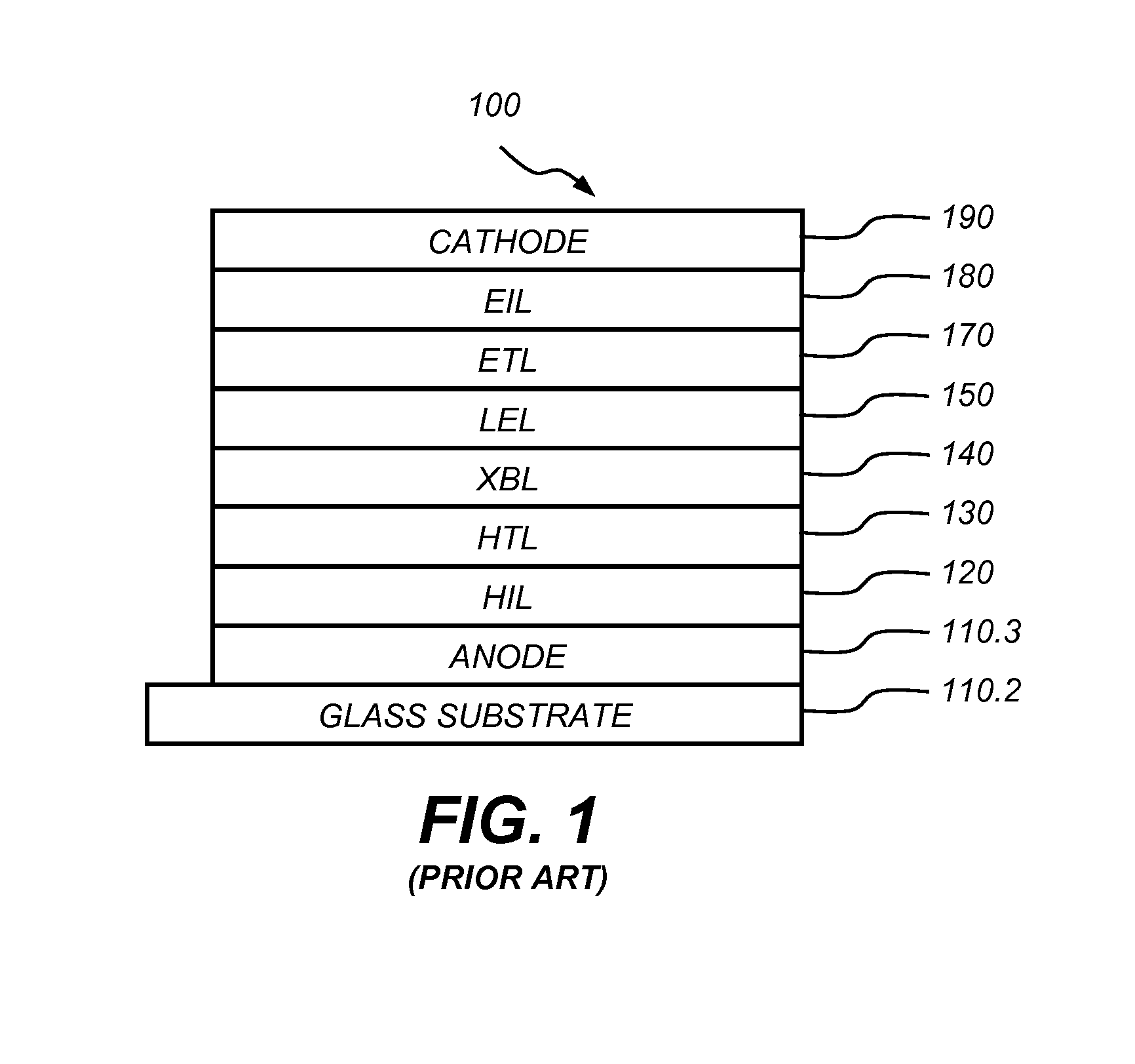
[0063]The preparation of a conventional OLED (Device 1) is as follows: A 1.1 mm thick glass substrate (refractive index 1.52) coated with a transparent indium-tin-oxide (ITO) conductive layer was cleaned and dried using a commercial glass scrubber tool. The thickness of ITO is about 100 nm and the sheet resistance of the ITO is about 30 Ω / square. The ITO surface was subsequently treated with oxidative plasma to condition the surface as an anode. A layer of CFx, 1 nm thick, was deposited on the clean ITO surface as the anode buffer layer by decomposing CHF3 gas in an RF plasma treatment chamber. The substrate was then transferred into a vacuum deposition chamber for deposition of all other layers on top of the substrate. The following layers were deposited in the following sequence by evaporation from a heated boat under a vacuum of approximately 10−6 Torr:

[0064]a) a hole-injecting layer (HIL), 10 nm thick, including hexaazatriphenylene hexacarbonitrile (HAT—CN);

[00...


PUM

PropertyMeasurementUnit
diameteraaaaaaaaaa
refractive indexaaaaaaaaaa
mean cavity diameteraaaaaaaaaa

Abstract

A method of manufacturing a micro-lens array and light-emitting device, comprising forming a first structured polymer film with close packed surface cavities having a mean diameter of less than 20 micrometers and a relatively lower surface energy surface, forming a transparent second structured film with an array of microlenses formed thereon corresponding to the cavities of the first structured film, wherein the second structured film comprises a relatively high surface energy material and has a refractive index greater than 1.45, and wherein the microlenses are randomly distributed, separating the second structured film with the micro-lens array from the first structured polymer film, and attaching the second structured film to a transparent substrate or cover of a light-emitting device through which light is emitted. Use of microlens arrays formed from relatively high surface energy materials enables matching refractive index of microlens array to that of light-emitting devices substrate or cover through which light is emitted and relatively high elastic modulus providing good scratch resistance.

Description

FIELD OF THE INVENTION[0001]This invention relates to a light-emitting device having a micro-lens array, and more particularly to self-emissive light-emitting devices having a high fill-factor micro-lens array in optical contact with a transparent substrate or cover of the light-emitting device, and a method of fabricating the high fill-factor micro-lens array.BACKGROUND OF THE INVENTION[0002]Light-emitting devices comprising self-emissive thin film light emitting elements such as organic light emitting diodes (OLEDs) represent an attractive technology for flat panel display and solid-state lighting. OLED devices generally can have two formats known as small molecule devices such as disclosed in U.S. Pat. No. 4,476,292 and polymer OLED devices such as disclosed in U.S. Pat. No. 5,247,190. Either type of OLED device may include, in sequence, an anode, an organic EL element, and a cathode. The organic EL element disposed between the anode and the cathode commonly includes an organic h...

Claims


Application Information

Patent Timeline
Patent Type & Authority Applications(United States)
IPC IPC(8): F21V5/04B29D11/00
CPCB29D11/00365B29D11/00807G02B3/0006
Inventor CHARI, KRISHNANLANDER, CHARLES W.LIAO, LIANG-SHENGYACOBUCCI, PAUL D.
Owner GLOBAL OLED TECH
Why Eureka
Try Eureka