The two major problems associated with secondary
zinc-air batteries, however, are limited total power and poor rechargeability / cycle lifetime.
The main reason for the low power of
zinc-air batteries is believed to be related to the inefficiency of the catalytic reaction to reduce
oxygen in the air electrodes.
Poor
accessibility of the catalyst and the local microstructural environment around the catalyst and adjoining carbon reduces the efficiency of the
oxygen reduction.
Rechargeability is also a problem with
zinc-air batteries.
Specifically, it is believed that
corrosion of the carbon used for the electrocatalyst in these systems leads to a loss incapacity and hence, a decreased
discharge time.
A significant obstacle to the wide-scale commercialization of such devices is the need for highly efficient electrocatalyst materials for this conversion process.
The critical issues that must be addressed for the successful commercialization of
fuel cells are
cell cost,
cell performance and operating lifetime.
Platinum metal is very expensive and a significant cost reduction in the electrocatalyst is necessary for these cells to become economically viable.
However, reducing the amount of
precious metal is not a suitable solution because there is also a strong demand for improved
cell performance which relies on the presence of the
platinum electrocatalyst.
The major technical challenge is improving the performance of the
cathode with air as the oxidant.
The inability to control the fundamental electrocatalyst
powder characteristics is a major obstacle for the future development of
energy storage and production devices.
The foregoing methods generally result in
poor control over the composition and
microstructure of the electrocatalytic materials, as well as
poor control over the dispersibility and surface area of the active species on the carbon surface.
Further,
alloy compositions such as
platinum /
ruthenium used for
oxygen reduction in a fuel cell are not made in a consistently reproducible fashion.
The inability to control the fundamental
powder characteristics is a major obstacle to the development of more efficient electrocatalyst materials.
A degree of homogeneity in materials is often not obtainable by traditional forming methods such as liquid
precipitation.
It is believed that higher oxidation states are detrimental to electrocatalyst
powder activity.
In extreme cases, some generators cannot atomize fluids with even moderate particle loadings or high viscosities
It is difficult to change particle size without varying the liquid or
airflow rates.
However, these types of atomizers have difficulty atomizing high
viscosity fluids or fluids with high particle loading.
The drawback to this
system of scaling is that increasing the
nozzle size increases the particle size.
Other problems encountered when using submerged ultrasonic transducers is the
coating of the
transducer discs with the particles over time.
The
nozzle is capable of higher atomization rates but increasing the liquid flow rate through the
nozzle does not increase the
production rate on horizontal tubular hot-wall reactors.
The majority of losses occur upon introducing the
aerosol into the furnace.
The low production rates for the
metal carbon precursor composition are due to the poor atomization of carbon suspensions with submerged ultrasonics.
Thus, particle characteristics cannot be de-coupled from the carrier gas flow rate.
The velocity of the particles as they leave the generation zone can be quite large which may lead to unwanted particle losses due to impaction.
The major
disadvantage of this approach for particles less than 5 microns is the low aerosol loading (
low mass of product per volume of gas) making this an expensive method for powder production.
The major
disadvantage is the
large droplet size which leads to losses of materials on reactor walls and other surfaces making this an expensive method for powder production.
Most spray dryers, however, are unable to achieve the high temperatures needed for the reduction of
platinum since maximum inlet temperatures are usually limited to about 600.degree. F.
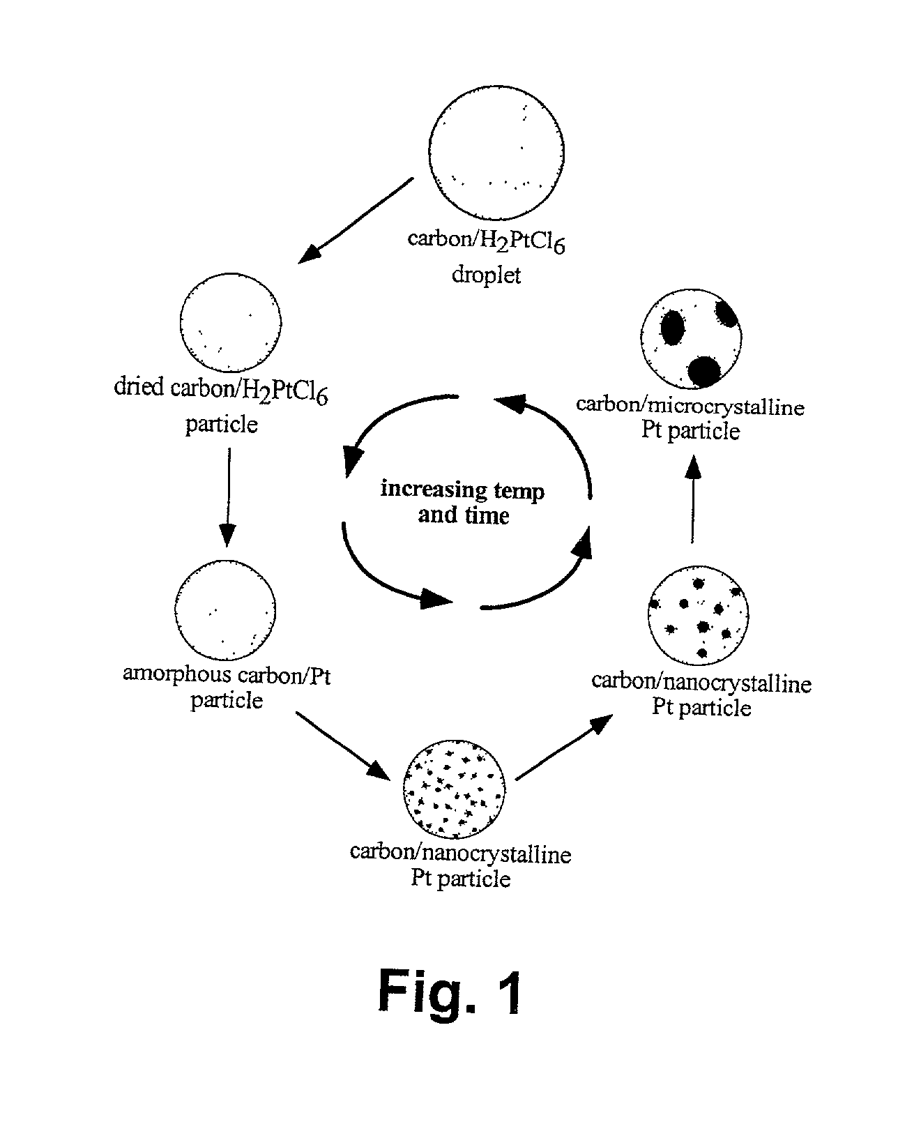
In addition, since the particles experience the lowest temperature in the beginning of the time-
temperature curve and the highest at the end, the possibility of precursor
surface diffusion and agglomeration is high and therefore the
decomposition of the precursor is more difficult compared to that of a highly dispersed precursor.
This is important, as most spray dryers are not capable of reaching the higher temperatures that are required for conversion of some of the precursor salts used.
Therefore, the electrocatalyst particles reach the highest temperature for relatively short time, which does not allow for significant precursor migration or
surface diffusion.
However, not all liquid precursors atomize well using an ultrasonic
transducer disk, such as carbon colloidal carbon solutions.
Conical tip nozzles have a spray pattern that is too wide fortubular systems, and
low frequency ultrasonic nozzles produce droplets too large to dry in
sufficient time.
Additionally, the conical nozzles lose a small amount to the gas introduction screens and the reactor tube walls.
However,
chloride salts may lead to detrimental catalytic properties over time.
The use of a liquid organic carbon precursor typically results in
amorphous carbon, which is not desirable for most electrocatalyst applications.
A precursor that is unstable will settle in the feed reservoir during the course of the
processing, resulting in droplets of varying composition, and ultimately affect the catalyst powder characteristics.
Nanometer-sized particles are difficult to produce in the presence of other particles while maintaining control of their dispersion on a
support surface.
Excess surfactants, particularly high molecular weight surfactants, can remain on the electrocatalyst particle surface and degrade the catalytic activity if not fully removed.
Shorter diffusional distances and lower diffusional barriers will lead to a higher rate of drain for this type of device.
Depending upon the density of the particle compound, however, particles with a
high density relative to the liquid in which they are dispersed and with a size in excess of about 0.5 .mu.m cannot be suspended in a liquid that has a sufficiently low
viscosity to be deposited using a direct-write tool, particularly an ink-jet device.
However, such devices have primarily been used to deposit inks of soluble dyes.
However, some
filtration of suspensions may occur if the particles are too large to pass through the channels or onboard filters.
C. A decrease in surface area is undesirable as it directly relates to the decrease in gas
diffusion through this lay
The drain rate is higher because once the kinetic limitation of the electrocatalyst is removed by using a more effective catalyst material, the next limitation on the catalytic conversion is the rate at which the species can diffuse between
layers.
It is expected that when decreasing feature size and
layer thickness in the
air cathode there will be a point at which further reduction in size will be detrimental to battery performance.
At these sizes it is possible that certain parameters such as pH, concentration, and
electric field gradients may dominate the performance of the device and possibly be detrimental.
One of the problems associated with batteries that use electrolytes is
carbonate formation from CO.sub.2.
The
molar volume increase on formation of MCO.sub.3 from MO on reaction with CO.sub.2 is considerable which may result in restricted
mass transport of O.sub.2 in the cell depending on the
porosity and other factors.
Metal-air rechargeable batteries were previously limited by problems with the air
electrode.
The ideal case is to supply pure
hydrogen to the PEMFC in which case there is no need for a reformer, but this is unlikely to be the case for the foreseeable future due to a lack of an existing
hydrogen distribution infrastructure.
However, due to the unreliability of reformers, which could produce a temporary increase in CO concentration and completely destroy the Pt / C catalysts, an
alloy catalyst is typically used containing
ruthenium / platinum
alloy on carbon (PtRu / C).
The cost and performance of these
precious metal-based electrocatalysts is the major contributor to the cost and performance of the fuel cell.
(See FIG. 6) The construction of the 3-phase interface has been a problem for a long time in electrochemical systems in general.
Issues associated with the performance of the PEM include the temperature of its operation and its
mechanical strength.
For a given polarization curve, operating at lower
voltage generally leads to lower efficiency, but requires a smaller cell (because the
power density is higher) and therefore smaller capital costs, but higher operating costs.
More platinum is better, but increasing the amount of platinum significantly contributes to the cost.
This current palette of materials that an MEA designer has to choose from is very limited.
Existing attempts at achieving this ideal situation are hindered by the lack of engineered particles, the limited printing processes dictated by the types of materials available and the types of structures derived from conventional materials.
However, the characteristics of these particles simply do not allow for straightforward fabrication of the optimum structures.
A major constraint on the life of a battery is the peak power requirement where the
energy storage in the battery is compromised for a burst of high power.
However a limitation of the double layer capacitors is the low
cell voltage, limited to 1 V for aqueous electrolytes and 2.5 V for organic electrolytes.
Thus, carbon is a typical material used as the
electrode due to its
high surface area, low cost and ready availability.
The cost of these electrodes has however been a
limiting factor in the rapid development of these electrodes commercially.

