Catalyst carrier, catalyst and process for producing the same

a catalyst and carrier technology, applied in the direction of catalyst carriers, physical/chemical process catalysts, cell components, etc., can solve the problems of low heat resistance of carbon, the inability of catalysts obtainable by using the carrier carbon to secure sufficient catalytic ability, and the technical limit of the particle diameter of the carrier carbon, etc., to achieve excellent heat resistance and high catalytic ability without increasing the specific surface area

Inactive Publication Date: 2010-12-30
SHOWA DENKO KK
View PDF26 Cites 31 Cited by
  • Summary
  • Abstract
  • Description
  • Claims
  • Application Information

AI Technical Summary

Benefits of technology

[0024]The catalyst carrier of the present invention has excellent heat resistance and can exert high catalytic ability without increasing the specific surface area.

Problems solved by technology

However, the diminishing of the particle diameter of the carrier carbon has the technical limits.
The catalyst obtainable by using the carrier carbon cannot secure sufficient catalytic ability.
Furthermore, the carbon has low heat resistance, and the carrier carbon corrodes and disappears with running the reaction in a fuel cell, so the catalyst metal particles such as Pt and the like which are supported on the carrier carbon are liberated from the carrier to cause a phenomenon such that the catalyst metal is flocculated.
However, there is no change in the structure that platinum and the like are directly supported on the carbon carrier, which suffers corrosion and disappearance in the noble electric potential environment, so the corrosion resistance is not vastly improved even by the above technique.

Method used


Image

  • Catalyst carrier, catalyst and process for producing the same
  • Catalyst carrier, catalyst and process for producing the same
  • Catalyst carrier, catalyst and process for producing the same

Examples


example 1

1. Preparation of Catalyst Carrier

[0162]4.96 g (81 mmol) of niobium carbide, 1.25 g (10 mmol) of niobium oxide and 0.54 g (5 mmol) of niobium nitride were fully mixed and heated in a nitrogen atmosphere at 1600° C. for 3 hr to prepare 2.70 g of niobium carbon nitride. The resulting sintered niobium carbon nitride was pulverized by a ball mill.

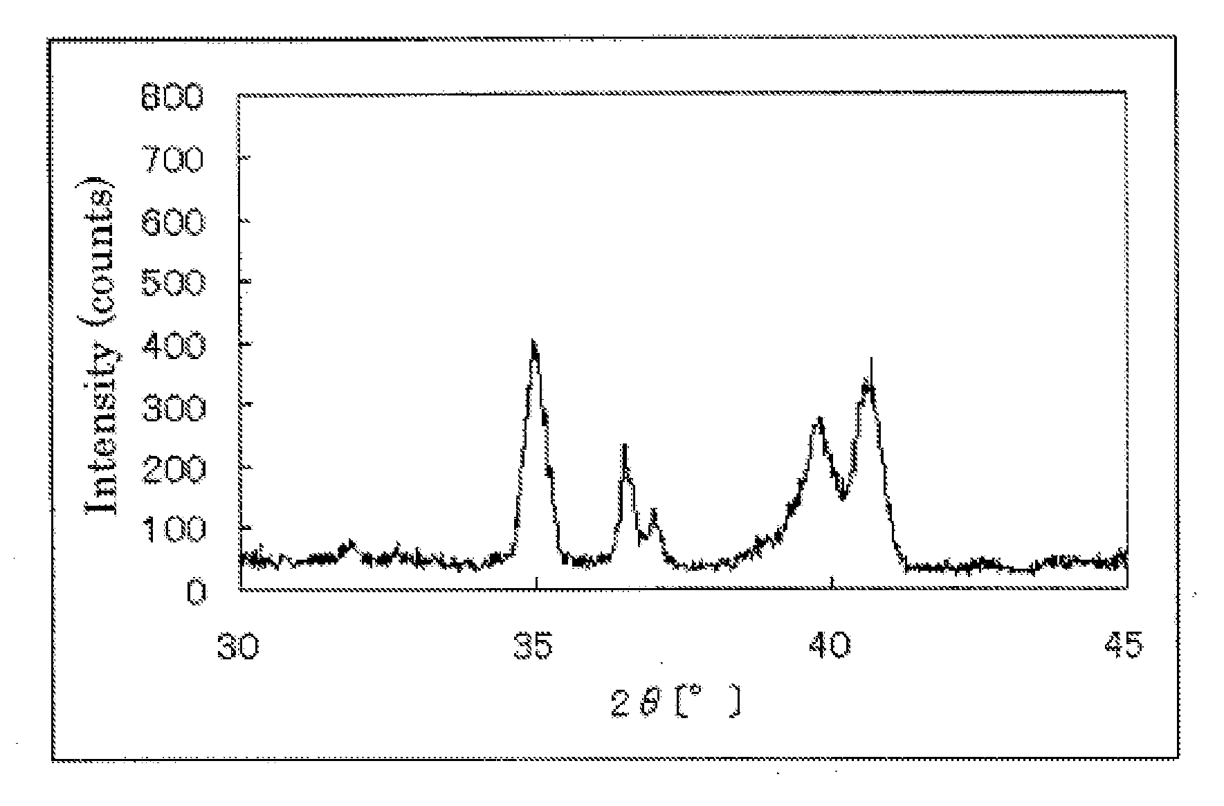
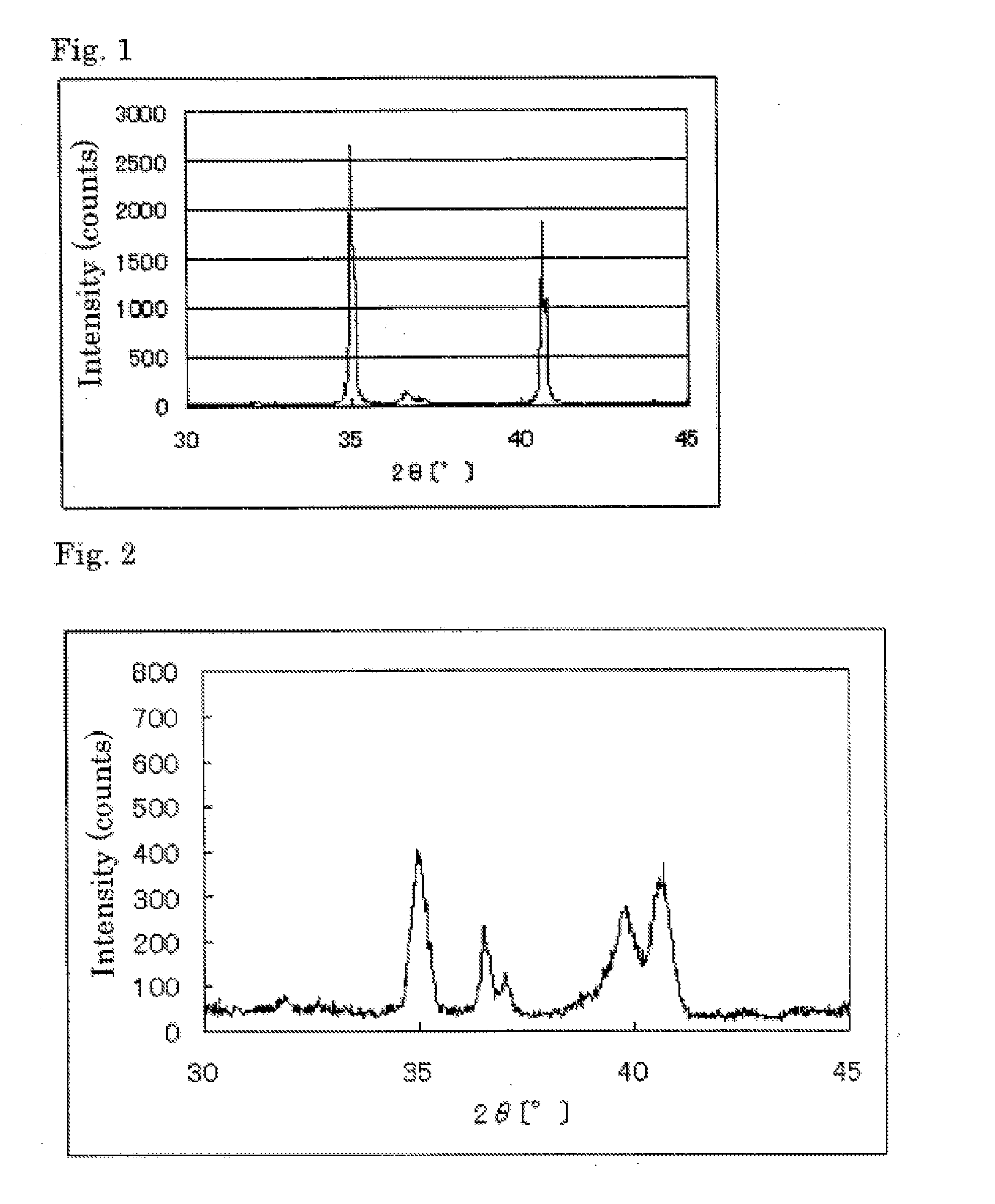
[0163]1.05 g of the niobium carbon nitride was heated in a tube-like furnace while feeding an argon gas containing 1% by volume of oxygen gas at 800° C. for 1 hr, and thereby 1.12 g of a niobium oxycarbonitride (hereinafter referred to “catalyst carrier (1)”) was prepared.

[0164]The powder X-ray diffraction spectrum of the resulting catalyst carrier (1) is shown in Table 1. At the diffraction angle 2θ in the range of 33° to 43°, four diffraction line peaks were observed. The element analysis results of the catalyst carrier (1) are shown in Table 1.

TABLE 1The element analysis results of the catalyst carrier (1) (wt % ; the parenthetic number is a...

example 2

1. Preparation of Catalyst (Method of Synthesizing a 2.5% by Weight Platinum Catalyst)

[0181]0.975 g of the niobium oxycarbonitride (the pulverized one was used: particle diameter of 100 nm) prepared in Example 1 was added to 100 ml of distilled water and shaken for 30 min by an ultrasonic cleaner. The suspension was put on a hot plate and kept at a liquid temperature of 80° C. with stirring. To the suspension, sodium carbide (0.043 g) was added.

[0182]To 25 ml of distilled water, 67 mg (0.134 mmol: 25 mg in terms of the platinum amount) of platinic chloride (H2PtCl6.6H2O) was dissolved to prepare a solution. The solution was slowly added to the suspension over 30 min (the solution temperature was kept at 80° C.). After completion of the dropping, the suspension, as it is, was stirred at 80° C. for 2 hr.

[0183]Next, 5 ml of a formaldehyde aqueous solution (trade one: 37%) was slowly added to the suspension. After completion of the addition, the suspension, as it is, was stirred at 80° ...

example 3

1. Preparation of Catalyst carrier

[0204]5.88 g (56 mmol) of niobium carbide, 0.87 g (5 mmol) of ferrous acetate and 5.14 g (48 mmol) of niobium nitride were fully mixed and heated in a nitrogen atmosphere at 1600° C. for 3 hr to prepare 10.89 g of iron and niobium-containing carbon nitride. Since the resulting iron and niobium-containing carbon nitride was sintered one, it was pulverized by a ball mill.

[0205]1.00 g of the iron and niobium-containing carbon nitride was heat-treated in a tube-like furnace while feeding a nitrogen gas containing 1% by volume of oxygen gas and 0.8% by volume of hydrogen gas at 900° C. for 6 hr, and thereby 1.24 g of a iron (5% by mole) and niobium-containing oxycarbonitride (hereinafter referred to “catalyst carrier (5)”) was prepared.

[0206]The powder X-ray diffraction spectrum of the resulting catalyst carrier (5) is shown in Table 12. The element analysis results of the catalyst carrier (5) are shown in Table 3.

TABLE 3Example 3NbFeCNOCompositionNbFeC0...


PUM

PropertyMeasurementUnit
particle diameteraaaaaaaaaa
temperatureaaaaaaaaaa
particle diameteraaaaaaaaaa

Abstract

The present invention provides a catalyst carrier having excellent durability and capable of attaining high catalytic ability without increasing the specific surface area thereof, and a catalyst obtainable by using the catalyst carrier. The catalyst carrier of the present invention comprises a metal oxycarbonitride, preferably the metal contained in the metal oxycarbonitride comprises at least one selected from the group consisting of niobium, tin, indium, platinum, tantalum, zirconium, copper, iron, tungsten, chromium, molybdenum, hafnium, titanium, vanadium, cobalt, manganese, cerium, mercury, plutonium, gold, silver, iridium, palladium, yttrium, ruthenium, lanthanum, cerium, praseodymium, neodymium, promethium, samarium, europium, gadolinium, terbium, dysprosium, holmium, erbium, thulium, ytterbium, lutetium, and nickel. Moreover, the catalyst of the present invention comprises the catalyst carrier and a catalyst metal supported on the catalyst carrier.

Description

TECHNICAL FIELD[0001]The present invention relates to a catalyst carrier, a catalyst and a process for producing the catalyst, more specifically, it relates to a catalyst carrier comprising a metal oxycarbonitride, a catalyst obtainable using the carrier and a process for producing the catalyst.TECHNICAL BACKGROUND[0002]Fuel cells are classified into various types in accordance with the kind of an electrolyte or the kind of an electrode. Typical examples are an alkali type, a phosphoric acid type, a molten carbonate type, a solid electrolyte type and a solid polymer type. Among them, the solid polymer type fuel cell capable of operating at a temperature of from a low temperature of about −40° C. to about 120° C. has been in the spotlight, and recently, the development and practical use thereof has been advanced as power sources having low environmental pollution used in automobiles. Driving sources for cars and fixed electric sources have been studied as the use of the solid polymer...

Claims


Application Information

Patent Timeline
Patent Type & Authority Applications(United States)
IPC IPC(8): B01J32/00C01B31/00C01F17/00B01J21/18
CPCB01J27/22B01J27/24B01J35/0033B01J37/0036H01M4/9075H01M4/92H01M4/925Y02E60/50B01J37/14B01J37/02
Inventor MONDEN, RYUJIKUROZUMI, TADATOSHISHISHIKURA, TOSHIKAZU
Owner SHOWA DENKO KK
Why Eureka
Try Eureka