
Humic acid-bonded metal foil film current collector and battery and supercapacitor containing same

a technology of metal foil film and current collector, which is applied in the direction of cell components, electrochemical generators, electrode manufacturing processes, etc., to achieve the effect of increasing the length or width of the planar molecules or sheets

Active Publication Date: 2018-02-22
GLOBAL GRAPHENE GRP INC
View PDF5 Cites 26 Cited by
  • Summary
  • Abstract
  • Description
  • Claims
  • Application Information

AI Technical Summary

Benefits of technology

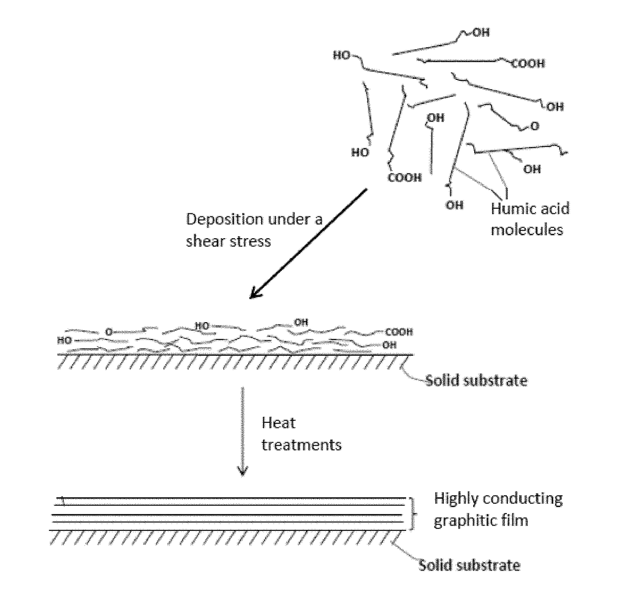
The present invention provides a highly oriented humic acid-bonded metal foil current collector for use in batteries or supercapacitors. The current collector comprises a thin metal foil with a thickness of 1-30 μm and two opposed but substantially parallel primary surfaces. A thin film of highly oriented humic acid or a mixture of humic acid and graphene sheets is bonded to one or both of the primary surfaces. The thin film has a thickness of 20 nm to 2 μm and an oxygen content of 1% to 10%. The thin film can be chemically bonded to the metal foil without using a binder or adhesive. The metal foil can be selected from copper, titanium, nickel, stainless steel, al foil, or a combination thereof. The thin film has an oxygen content of 1% to 5% by weight and an inter-planar spacing of 0.335 to 0.70 nm. The thin film or the graphitic film derived therefrom has an electrical conductivity of 10,000 S / cm or higher. The current collector has high orientation and excellent performance.

Problems solved by technology

Unfortunately, upon repeated charges and discharges, the lithium metal resulted in the formation of dendrites at the anode that ultimately caused internal shorting, thermal runaway, and explosion.
As a result of a series of accidents associated with this problem, the production of these types of secondary batteries was stopped in the early 1990's giving ways to lithium-ion batteries.
Even now, cycling stability and safety concerns remain the primary factors preventing the further commercialization of Li metal batteries (e.g. Lithium-sulfur and Lithium-transition metal oxide cells) for EV, HEV, and microelectronic device applications.
Although lithium-ion (Li-ion) batteries are promising energy storage devices for electric drive vehicles, state-of-the-art Li-ion batteries have yet to meet the cost, safety, and performance targets (such as high specific energy, high energy density, good cycle stability, and long cycle life).
However, there are several major issues associated with state-of-the-art current collectors: (a) Due to easy creasing and tearing, thinner foils tend to be more expensive and harder to work with; (b) Current collectors must be electrochemically stable with respect to the cell components over the operating potential window of the electrode.
In practice, continued corrosion of the current collectors mainly by the electrolyte can lead to a gradual increase in the internal resistance of the battery, resulting in persistent loss of the apparent capacity or poor cycling life: (c) Oxidation of metal current collectors is a strong exothermic reaction that can significantly contribute to thermal runaway of a lithium battery.
Although individual graphene sheets / platelets can have a relatively high electrical conductivity (within the confine of that 0.5-5 μm), the resulting graphene-binder resin composite layer is relatively poor in electrical conductivity (typically <100 S / cm and more typically <10 S / cm).
Unfortunately, this binder resin layer is electrically insulating and the resulting detrimental effect seems to have been totally overlooked by prior workers.
[Ref 2] does not seem to have used a binder resin in forming an aluminum foil coated with discrete graphene oxide sheets, this graphene oxide-coated Al foil has its own problem.
It is well-known in the art that aluminum oxide (Al2O3) readily forms on surfaces of an aluminum foil and cleaning with acetone or alcohol is not capable of removing this passivating layer of aluminum oxide or alumina.
This aluminum oxide layer is not only electrically and thermally insulating, but actually is not resistant to certain types of electrolyte.
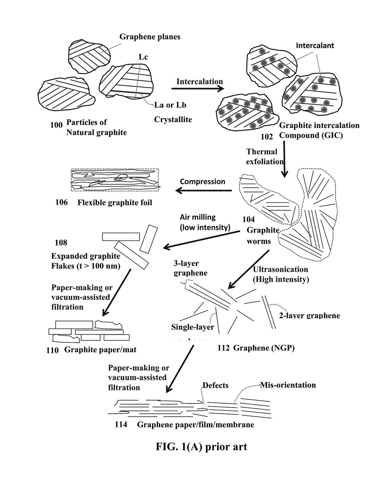
There are several major problems associated with the most commonly used process for producing graphene (i.e. the chemical oxidation / intercalation process):(1) The process requires the use of large quantities of several undesirable chemicals, such as sulfuric acid, nitric acid, and potassium permanganate or / and sodium chlorate.(2) The thermal exfoliation requires a high temperature (typically 800-1,050° C.) and, hence, is a highly energy-intensive process.(3) The approach requires a very tedious washing and purification step.
During the high-temperature exfoliation, the residual intercalate species retained by the flakes decompose to produce various species of sulfuric and nitrous compounds (e.g., NOx and SOx), which are undesirable.
The whole process is slow, tedious, and energy-intensive, and the resulting graphene is typically a single layer graphene or few-layer graphene (up to 5 layers maximum since the underlying Cu / Ni layer loses its effectiveness as a catalyst).
Although Bhardwaj, et al claimed that “The graphene may reduce the manufacturing cost and / or increase the energy density of a battery cell,” no experimental data was presented to support their claim.
Contrary to this claim, the CVD graphene is a notoriously expensive process and even a single-layer of CVD graphene film would be significantly more expensive than a sheet of Cu or Al foil given the same area (e.g. the same 5 cm×5 cm).
A stack of hundreds or thousands of mono-layer or few-layer graphene films as suggested by Bhardwaj, et al would mean hundreds or thousands times more expensive than a Cu foil current collector.
This cost would be prohibitively high.
Further, the high contact resistance between hundreds of CVD graphene films in a stack and the relatively low conductivity of CVD graphene would lead to an overall high internal resistance, nullifying any potential benefit of using thinner films (1 μm of graphene stack vs.
The above discussions have clearly shown that all three forms of the graphene-enhanced or graphene-based current collector do not meet the performance and cost requirements for use in a battery or supercapacitor.

Method used


Image

  • Humic acid-bonded metal foil film current collector and battery and supercapacitor containing same
  • Humic acid-bonded metal foil film current collector and battery and supercapacitor containing same
  • Humic acid-bonded metal foil film current collector and battery and supercapacitor containing same

Examples


example 1

Humic Acid and Reduced Humic Acid from Leonardite

[0162]Humic acid can be extracted from leonardite by dispersing leonardite in a basic aqueous solution (pH of 10) with a very high yield (in the range of 75%). Subsequent acidification of the solution leads to precipitation of humic acid powder. In an experiment, 3 g of leonardite was dissolved by 300 ml of double deionized water containing 1M KOH (or NH4OH) solution under magnetic stirring. The pH value was adjusted to 10. The solution was then filtered to remove any big particles or any residual impurities.

[0163]The resulting humic acid dispersion, containing HA alone or HA with the presence of graphene oxide sheets (GO prepared in Example 3 described below), was coated onto a Cu foil or Ti foil surface form a series of HA-bonded Cu foil or Ti foil films for subsequent heat treatments to obtain Type-A current collectors.

[0164]For comparison, similar films were cast onto glass surface and then peeled off prior to subsequent heat trea...

example 2

Preparation of Humic Acid from Coal and HA-Bonded Metal Foil Current Collectors

[0165]In a typical procedure, 300 mg of coal was suspended in concentrated sulfuric acid (60 ml) and nitric acid (20 ml), and followed by cup sonication for 2 h. The reaction was then stirred and heated in an oil bath at 100 or 120° C. for 24 h. The solution was cooled to room temperature and poured into a beaker containing 100 ml ice, followed by a step of adding NaOH (3M) until the pH value reached 7.

[0166]In one experiment, the neutral mixture was then filtered through a 0.45-mm polytetrafluoroethylene membrane and the filtrate was dialyzed in 1,000 Da dialysis bag for 5 days. For the larger humic acid sheets, the time can be shortened to 1 to 2 h using cross-flow ultrafiltration. After purification, the solution was concentrated using rotary evaporation to obtain solid humic acid sheets. These humic sheets alone and their mixtures with graphene sheets were re-dispersed in a solvent (ethylene glycol an...

example 3

Preparation of Graphene Oxide (GO) Sheets from Natural Graphite Powder

[0167]Natural graphite from Ashbury Carbons was used as the starting material. GO was obtained by following the well-known modified Hummers method, which involved two oxidation stages. In a typical procedure, the first oxidation was achieved in the following conditions: 1100 mg of graphite was placed in a 1000 mL boiling flask. Then, 20 g of K2S2O8, 20 g of P2O5, and 400 mL of a concentrated aqueous solution of H2SO4 (96%) were added in the flask. The mixture was heated under reflux for 6 hours and then let without disturbing for 20 hours at room temperature. Oxidized graphite was filtered and rinsed with abundant distilled water until a pH value >4.0 was reached. A wet cake-like material was recovered at the end of this first oxidation.

[0168]For the second oxidation process, the previously collected wet cake was placed in a boiling flask that contains 69 mL of a concentrated aqueous solution of H2SO4 (96%). The f...


PUM


Abstract

A humic acid-bonded metal foil current collector in a battery or supercapacitor, comprising: (a) a thin metal foil having two opposed but parallel primary surfaces; and (b) a thin film of humic acid (HA) or a mixture of HA and graphene, having hexagonal carbon planes, wherein HA or both HA and graphene are chemically bonded to at least one of the two primary surfaces; wherein the thin film has a thickness from 10 nm to 10 μm, an oxygen content from 0.01% to 10% by weight, an inter-planar spacing of 0.335 to 0.50 nm between hexagonal carbon planes, a physical density from 1.3 to 2.2 g / cm3, all hexagonal carbon planes being oriented substantially parallel to each other and parallel to the primary surfaces, exhibiting a thermal conductivity greater than 500 W / mK, and / or electrical conductivity greater than 1,500 S / cm when measured alone without the metal foil.

Description

FIELD OF THE INVENTION[0001]The present invention provides a current collector for a lithium battery or supercapacitor. The current collector is a metal foil bonded with a thin film of highly oriented humic acid or humic acid-derived highly conducting graphitic film.BACKGROUND[0002]This patent application is directed at a current collector that works with an anode electrode (anode active material layer) or a cathode electrode (cathode active material layer) of a lithium cell (e.g. lithium-ion cell, lithium-metal cell, or lithium-ion capacitor), a supercapacitor, a non-lithium battery (such as the zinc-air cell, nickel metal hydride battery, sodium-ion cell, and magnesium-ion cell), and other electrochemical energy storage cells. This application is not part of the anode active material layer or the cathode active material layer per se.[0003]The lithium-metal cell includes the conventional lithium-metal rechargeable cell (e.g. using a lithium foil as the anode and MnO2 particles as t...

Claims


Application Information

Patent Timeline
IPC IPC(8): H01M4/1393H01M4/04H01M4/66H01M4/133H01M4/583H01M10/0525H01G11/68H01G11/84C09K5/14C01B31/04C07D413/14
CPCH01M4/1393H01M4/0404H01M4/0471H01M4/661H01M4/662H01M4/133C07D413/14H01M10/0525H01G11/68H01G11/84C09K5/14C01B31/04H01M4/583H01M4/663H01M4/667H01M10/052H01M12/08C01B32/20H01G11/02H01G11/04H01G11/28H01G11/36H01G11/70H01M4/04H01M4/66Y02E60/10
Inventor ZHAMU, ARUNAJANG, BOR Z.
Owner GLOBAL GRAPHENE GRP INC
Learn More