
Method of Producing a Shape-Conformable Alkali Metal Battery Having a Conductive and Deformable Quasi-solid Polymer Electrode

a technology of quasi-solid polymer electrodes and shape-conformable alkali metal batteries, which is applied in the direction of cell components, electrochemical generators, transportation and packaging, etc., to achieve the effects of low overhead weight and volume, high active material mass loading, and high capacity

Active Publication Date: 2018-12-06
GLOBAL GRAPHENE GRP INC
View PDF0 Cites 13 Cited by
  • Summary
  • Abstract
  • Description
  • Claims
  • Application Information

AI Technical Summary

Benefits of technology

The present invention provides a method for making a flexible and shape-conformable lithium or sodium battery with high active material mass loading, low weight and volume, high capacity, and unprecedented energy density and power density. The battery can be a primary battery or a secondary battery. It includes a new type of electrode called a "sac-ode," which is a combination of a supercapacitor cathode and a lithium-ion or sodium-ion battery anode. This new battery has potential applications in various fields such as electronics, portable devices, and electric vehicles.

Problems solved by technology

This and several other batteries from different manufacturers were abandoned due to a series of safety problems caused by sharply uneven Li growth (formation of Li dendrites) as the metal was re-plated during each subsequent recharge cycle.
As the number of cycles increases, these dendritic or tree-like Li structures could eventually traverse the separator to reach the cathode, causing internal short-circuiting.
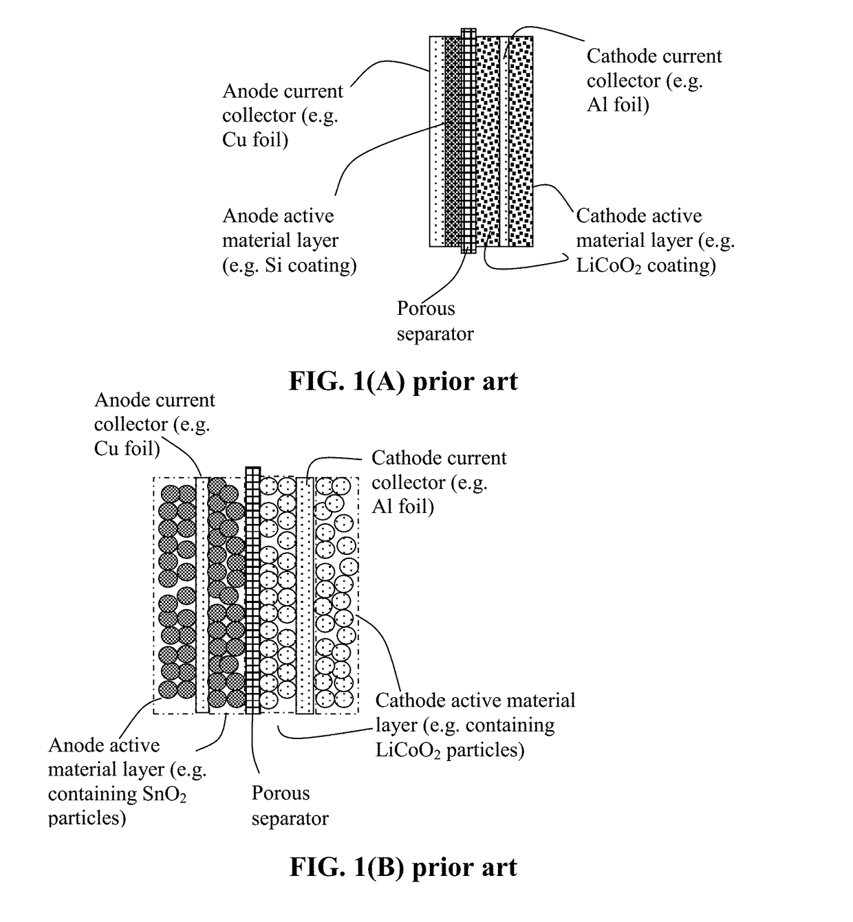
However, the use of graphite-based anodes in Li-ion batteries has several significant drawbacks: low specific capacity (theoretical capacity of 372 mAh / g as opposed to 3,860 mAh / g for Li metal), long Li intercalation time (e.g. low solid-state diffusion coefficients of Li in and out of graphite and inorganic oxide particles) requiring long recharge times (e.g. 7 hours for electric vehicle batteries), inability to deliver high pulse power (power density <<1 kW / kg), and necessity to use pre-lithiated cathodes (e.g. lithium cobalt oxide), thereby limiting the choice of available cathode materials.
Further, these commonly used cathodes have a relatively low specific capacity (typically <200 mAh / g).
However, the dramatic volume changes (up to 380%) of Si during lithium ion alloying and de-alloying (cell charge and discharge) often led to severe and rapid battery performance deterioration.
The performance fade is mainly due to the volume change-induced pulverization of Si and the inability of the binder / conductive additive to maintain the electrical contact between the pulverized Si particles and the current collector.
In addition, the intrinsic low electric conductivity of silicon is another challenge that needs to be addressed.
Although several high-capacity anode active materials have been found (e.g., Si), there has been no corresponding high-capacity cathode material available.
Current cathode active materials commonly used in Li-ion batteries have the following serious drawbacks:(1) The practical capacity achievable with current cathode materials (e.g. lithium iron phosphate and lithium transition metal oxides) has been limited to the range of 150-250 mAh / g and, in most cases, less than 200 mAh / g.(2) The insertion and extraction of lithium in and out of these commonly used cathodes rely upon extremely slow solid-state diffusion of Li in solid particles having very low diffusion coefficients (typically 10−8 to 10−′4 cm2 / s), leading to a very low power density (another long-standing problem of today's lithium-ion batteries).(3) The current cathode materials are electrically and thermally insulating, not capable of effectively and efficiently transporting electrons and heat.
The low thermal conductivity also implies a higher tendency to undergo thermal runaway, a major safety issue in lithium battery industry.
There are serious design and manufacturing issues that the lithium-ion battery industry does not seem to be aware of, or has largely ignored.
For instance, despite the high gravimetric capacities at the electrode level (based on the anode or cathode active material weight alone) as frequently claimed in open literature and patent documents, these electrodes unfortunately fail to provide batteries with high capacities at the battery cell or pack level (based on the total battery cell weight or pack weight).
This is due to the notion that, in these reports, the actual active material mass loadings of the electrodes are too low.
In addition, the high cost of lithium is a major issue.
However, these sodium-based devices exhibit even lower specific energies and rate capabilities than Li-ion batteries.
The required solid-state diffusion processes for sodium ions in a sodium-ion battery are even slower than the Li diffusion processes in a Li-ion battery, leading to excessively low power densities.
However, the use of metallic sodium as the anode active material is normally considered undesirable and dangerous because of dendrite formation, interface aging, and electrolyte incompatibility problems.
The low active material mass loading is primarily due to the inability to obtain thicker electrodes (thicker than 100-200 μm) using the conventional slurry coating procedure.
Contrarily, thicker samples tend to become extremely brittle or of poor structural integrity and would also require the use of large amounts of binder resin.
The low areal densities and low volume densities (related to thin electrodes and poor packing density) result in a relatively low volumetric capacity and low volumetric energy density of the battery cells.

Method used


Image

  • Method of Producing a Shape-Conformable Alkali Metal Battery Having a Conductive and Deformable Quasi-solid Polymer Electrode
  • Method of Producing a Shape-Conformable Alkali Metal Battery Having a Conductive and Deformable Quasi-solid Polymer Electrode
  • Method of Producing a Shape-Conformable Alkali Metal Battery Having a Conductive and Deformable Quasi-solid Polymer Electrode

Examples


example 1

on of Graphene Oxide (GO) and Reduced Graphene Oxide (RGO) Nano Sheets from Natural Graphite Powder

[0152]Natural graphite from Huadong Graphite Co. (Qingdao, China) was used as the starting material. GO was obtained by following the well-known modified Hummers method, which involved two oxidation stages. In a typical procedure, the first oxidation was achieved in the following conditions: 1100 mg of graphite was placed in a 1000 mL boiling flask. Then, 20 g of K2S2O8, 20 g of P2O5, and 400 mL of a concentrated aqueous solution of H2SO4 (96%) were added in the flask. The mixture was heated under reflux for 6 hours and then let without disturbing for 20 hours at room temperature. Oxidized graphite was filtered and rinsed with abundant distilled water until neutral pH. A wet cake-like material was recovered at the end of this first oxidation.

[0153]For the second oxidation process, the previously collected wet cake was placed in a boiling flask that contains 69 mL of a concentrated aque...

example 2

on of Pristine Graphene Sheets (Essentially 0% Oxygen)

[0157]Recognizing the possibility of the high defect population in GO sheets acting to reduce the conductivity of individual graphene plane, we decided to study if the use of pristine graphene sheets (non-oxidized and oxygen-free, non-halogenated and halogen-free, etc.) can lead to a conductive additive having a high electrical and thermal conductivity. Pre-lithiated pristine graphene was also used as an anode active material. Pristine graphene sheets were produced by using the direct ultrasonication or liquid-phase production process.

[0158]In a typical procedure, five grams of graphite flakes, ground to approximately 20 μm or less in sizes, were dispersed in 1,000 mL of deionized water (containing 0.1% by weight of a dispersing agent, Zonyl® FSO from DuPont) to obtain a suspension. An ultrasonic energy level of 85 W (Branson S450 Ultrasonicator) was used for exfoliation, separation, and size reduction of graphene sheets for a pe...

example 3

on of Prelithiated Graphene Fluoride Sheets as an Anode Active Material of a Lithium-Ion Battery

[0160]Several processes have been used by us to produce GF, but only one process is herein described as an example. In a typical procedure, highly exfoliated graphite (HEG) was prepared from intercalated compound C2F.xClF3. HEG was further fluorinated by vapors of chlorine trifluoride to yield fluorinated highly exfoliated graphite (FHEG). Pre-cooled Teflon reactor was filled with 20-30 mL of liquid pre-cooled ClF3, the reactor was closed and cooled to liquid nitrogen temperature. Then, no more than 1 g of HEG was put in a container with holes for ClF3 gas to access and situated inside the reactor. In 7-10 days a gray-beige product with approximate formula C2F was formed.

[0161]Subsequently, a small amount of FHEG (approximately 0.5 mg) was mixed with 20-30 mL of an organic solvent (methanol and ethanol, separately) and subjected to an ultrasound treatment (280 W) for 30 min, leading to th...


PUM

PropertyMeasurementUnit
electrical conductivityaaaaaaaaaa
thicknessaaaaaaaaaa

Abstract

Provided is method of preparing an alkali metal cell, the method comprising: (a) combining a quantity of an active material, a quantity of an electrolyte, and a conductive additive to form a deformable and conductive electrode material, wherein the conductive additive, containing conductive filaments, forms a 3D network of electron-conducting pathways and the electrolyte contains an alkali salt and an ion-conducting polymer dissolved or dispersed in a solvent; (b) forming the electrode material into a quasi-solid polymer electrode, wherein the forming includes deforming the electrode material into an electrode shape without interrupting the 3D network of electron-conducting pathways such that the electrode maintains an electrical conductivity no less than 10−6 S / cm; (c) forming a second electrode; and (d) forming an alkali metal cell by combining the quasi-solid electrode and the second electrode. The second electrode may also be a quasi-solid polymer electrode.

Description

FIELD OF THE INVENTION[0001]The present invention relates generally to the field of alkali metal batteries, including rechargeable lithium metal batteries, sodium metal batteries, lithium-ion batteries, sodium-ion batteries, lithium-ion capacitors and sodium-ion capacitors.BACKGROUND OF THE INVENTION[0002]Historically, today's most favorite rechargeable energy storage devices—lithium-ion batteries—actually evolved from rechargeable “lithium metal batteries” using lithium (Li) metal or Li alloy as the anode and a Li intercalation compound as the cathode. Li metal is an ideal anode material due to its light weight (the lightest metal), high electronegativity (−3.04 V vs. the standard hydrogen electrode), and high theoretical capacity (3,860 mAh / g). Based on these outstanding properties, lithium metal batteries were proposed 40 years ago as an ideal system for high energy-density applications. During the mid-1980s, several prototypes of rechargeable Li metal batteries were developed. A...

Claims


Application Information

Patent Timeline
Patent Type & Authority Applications(United States)
IPC IPC(8): H01M10/0525H01M4/60H01M4/62H01M4/40H01M4/38H01M10/0565H01M4/04H01G11/86H01G11/32H01G11/60H01G11/46H01G11/06
CPCH01M10/0525H01G11/36H01M4/625H01M4/405H01M4/381H01M10/0565H01M4/04H01G11/86H01G11/32H01G11/60H01G11/46H01G11/06H01G11/44H01G11/34H01M4/602H01G11/24H01G11/40H01G11/42H01G11/48H01G11/50H01M4/0404H01M4/131H01M4/133H01M4/134H01M4/136H01M4/137H01M4/1391H01M4/1393H01M4/1395H01M4/1397H01M4/1399H01M4/38H01M4/485H01M4/505H01M4/525H01M4/58H01M4/587H01M4/622H01M4/623H01M10/052H01M10/054Y02E60/10Y02T10/70
Inventor ZHAMU, ARUNAJANG, BOR Z.
Owner GLOBAL GRAPHENE GRP INC
Learn More