These parameters can also affect the quality of the resulting epitaxial layer, in terms of
chemical purity and number of defects present in the crystalline film.
LPE, however, has its limitations (e.g., LPE cannot produce very thin high-quality
layers, etc.), but is inexpensive and capable of growing many material compositions.
Of course, MBE has its disadvantages, such as the high-vacuum requirements, complex and costly equipment, and the
slow growth rate of the epitaxial layer.
However, these prior art crucibles have significant limitations.
The primary problems associated with existing crucibles are (1) low capacity, (2) lack of uniformity, (3) oval defect production, (4) short term flux transients, (5) long term flux transients, etc.
However, crucibles having a cylindrical configuration throughout tend to provide poor depositional uniformity because the
molecular beam emitted from the zero draft cylindrical orifice is too tightly focused or collimated upon the substrate holder.
However, crucibles having a conical configuration have
limited capacity, exhibit depletion effects, and are prone to flux transients (the volume of a cone is only ⅓ the volume of a cylinder with the same height and base area).
A
disadvantage with some hot lip source designs is that they produce a hydrodynamically unstable flux, they tend to produce undesirable levels of impurities due to enhanced
outgassing, and they often exhibit rapid depletion effects.
Generally, flux transients are a problem in
crucible designs having a conical configuration throughout.
These multi-piece chamber structures have significant limitations.
Leaking gas will not be cracked by the source and this results in a loss of efficiency.
Other problems found in prior art sources include generation of instabilities, high levels of N2 gas in the growth environment, and low levels of N1.
However, for some high temperature applications, such as growth of
Gallium Nitride crystals, the
quartz tube can melt and lose its shape.
Also,
quartz can contribute undesirable
Oxygen (O) and
Silicon (Si) gas into the growth environment
However, the species of
arsenic, i.e., As4, derived from heating elemental
arsenic or phosphorous are difficult to
handle and the
tetramer form leads to point defects or regions of high phosphorous or
arsenic concentrations in the growing layer.
Because of the inwardly directed transition area between the body portion and the
cracking portion of the
crucible used in such thermal crackers, it was not possible to make such crucibles for crackers out of PBN.
This severely limited the types of source materials which could be used in a thermal cracker, because the
tantalum or
titanium crucible is not suitable for use with liquid metal source materials, such as Silver (Ag), Aluminum (Al), Gold (Au),
Boron (B),
Barium (Ba),
Bismuth (Bi),
Cadmium (Cd), Cobolt (Co), Cesium (Cs),
Copper (Cu), Iron (Fe), Gallium (Ga),
Gadolinium (Gd),
Germanium (Ge), Mercury (Hg),
Indium (In),
Potassium (K),
Lanthanum (La),
Lithium (Li),
Sodium (Na),
Nickel (Ni), Lead (Pb),
Palladium (Pd),
Praseodymium (Pr),
Platinum (Pt),
Rubidium (Rb),
Antimony (Sb),
Scandium (Sc),
Selenium (Se),
Silicon (Si),
Tin (Sn),
Tellurium (Te),
Thallium (Tl),
Vanadium (V),
Ytterbium (Y), and
Zinc (Zn).
As a result, when the valve is closed, a large pressure build-up occurs in the chamber.
The excess release of
phosphorus into the MBE chamber is harmful to the MBE growth
system.
In addition, the MBE chamber requires several hours after such a pressure burst to recover to a proper
working pressure.
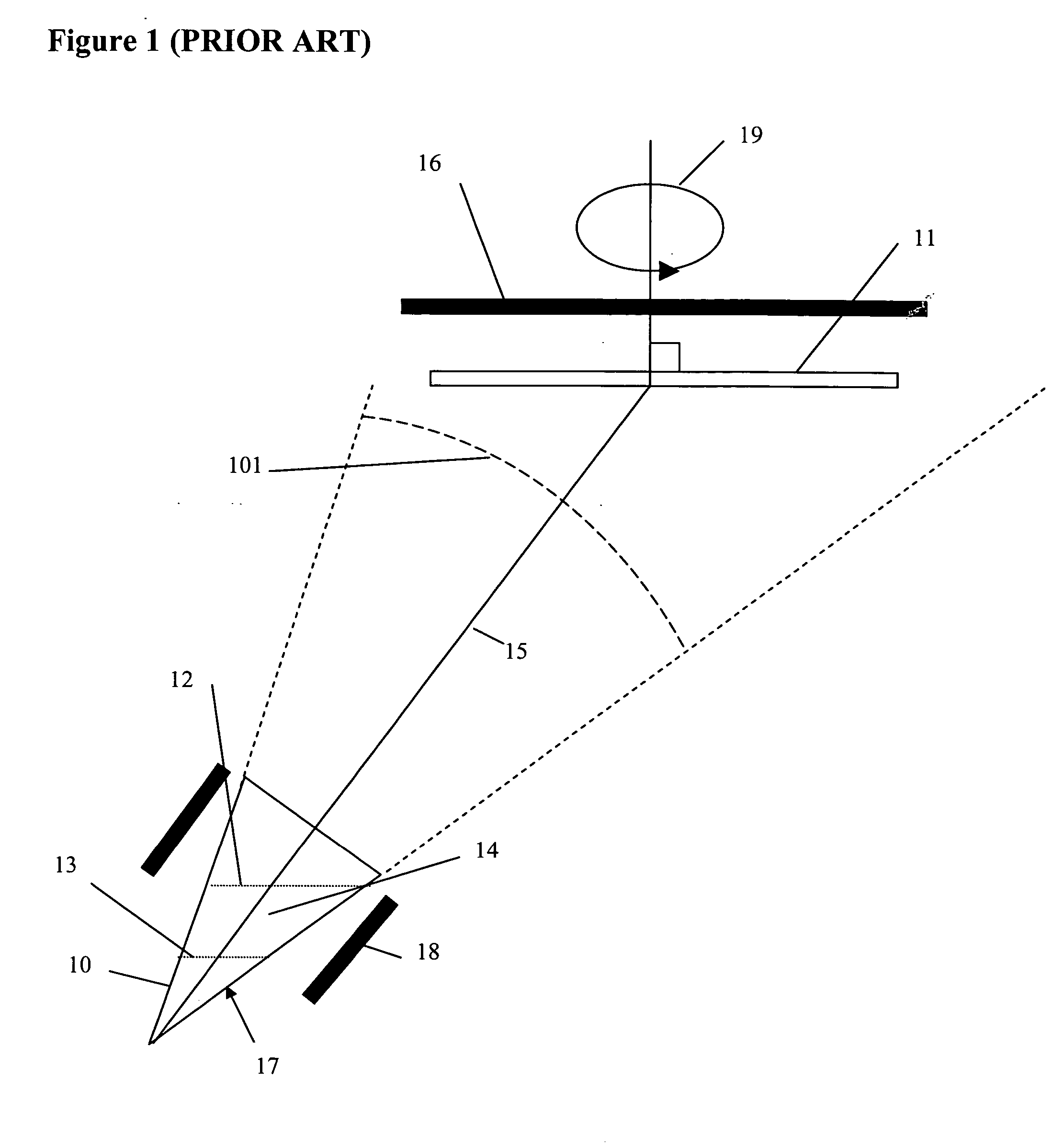
Although this method may be useful in some circumstances, there is a limited practical range over which this distance can be adjusted.
Errors in flux measurement can result in
layer thickness and compositions that do not meet specifications that adversely affect
wafer yields.
In addition, the metal fluxes cannot be measured in real-time during the MBE growth process leading to further errors and decreased
wafer yields.
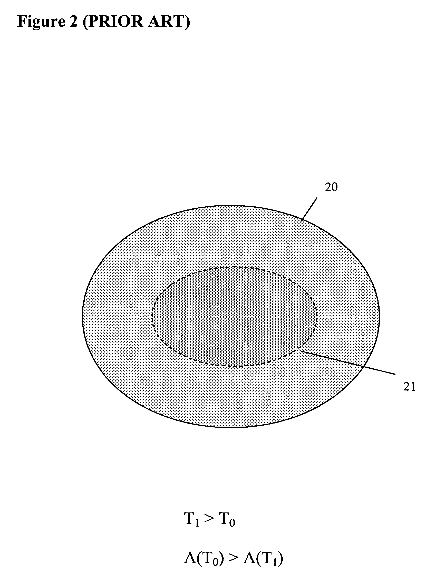
Lattice-matching of
semiconductor layers becomes problematic near the end of the life of the source charges as the metal surface areas reach a minimum area resulting in rapid changes in
metal evaporation rates with time.
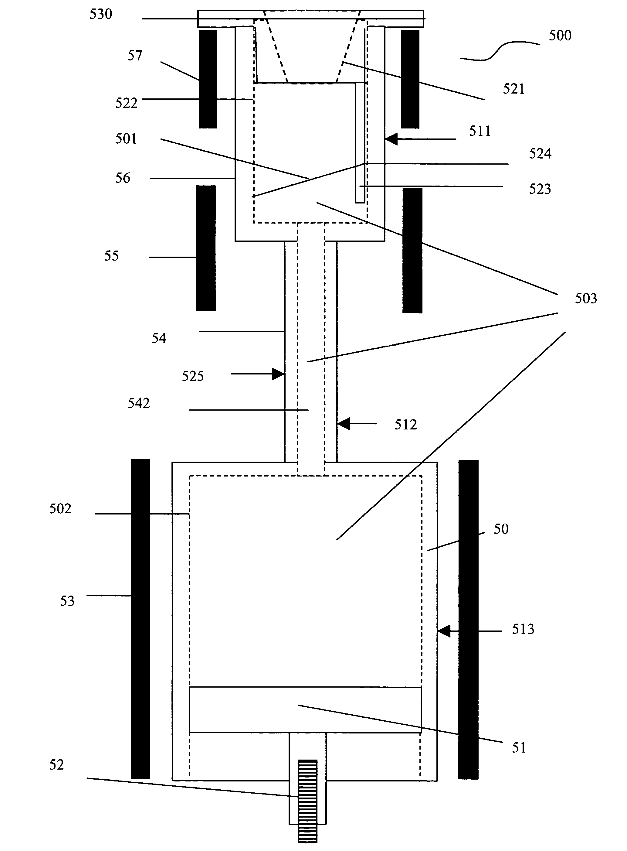
However this metal evaporator still has several problems.
Also this configuration leads to some focusing of the metal beam flux over the substrate as the metal surface recedes in the cylindrical crucible which adversely affects the deposition uniformity across the substrate.
Another problem with this
cell configuration is that the truncated conical crucible 31 is indirectly heated by the
radiant heater element 34 through the walls of the cylindrical crucible 30.
This leads to condensation of
metal droplets on the conical crucible that fall back by gravity into the metal evaporator which leads to numerous “
spitting” defects in the grown
layers.
The deposited metal uniformity across the substrate will also degrade with time due to the focusing affect of the nosecone as the metal surface recedes in the cylindrical crucible due to metal depletion from
evaporation.
Another problem of the single piece crucible design is that the narrow opening of the nosecone attached to the reservoir requires loading of small
solid pellets of the metal
source material thus reducing the loading volume of the
source material by approximately 50%.
The effect is further increased in hot lip cells because they are typically somewhat less efficient in their use of material.
There are numerous problems and disadvantages associated with the prior art liquid
metal evaporation sources discussed above.
For example, these prior art embodiments suffer from inconsistent evaporation and deposition rates, melt depletion, exhibit a need for frequent recalibration to accompany associated changes in MBE process rates, and small, low capacity crucibles that result in a low overall
throughput of substrate deposition.

