[0009]A more complete appreciation of the disclosure and many of the attendant advantages thereof will be readily obtained as the same becomes better understood by reference to the following detailed description when considered in connection with the accompanying drawings, wherein:
[0010]FIG. 1 is a
schematic view illustrating a toner manufacturing apparatus according to exemplary embodiments of the invention;
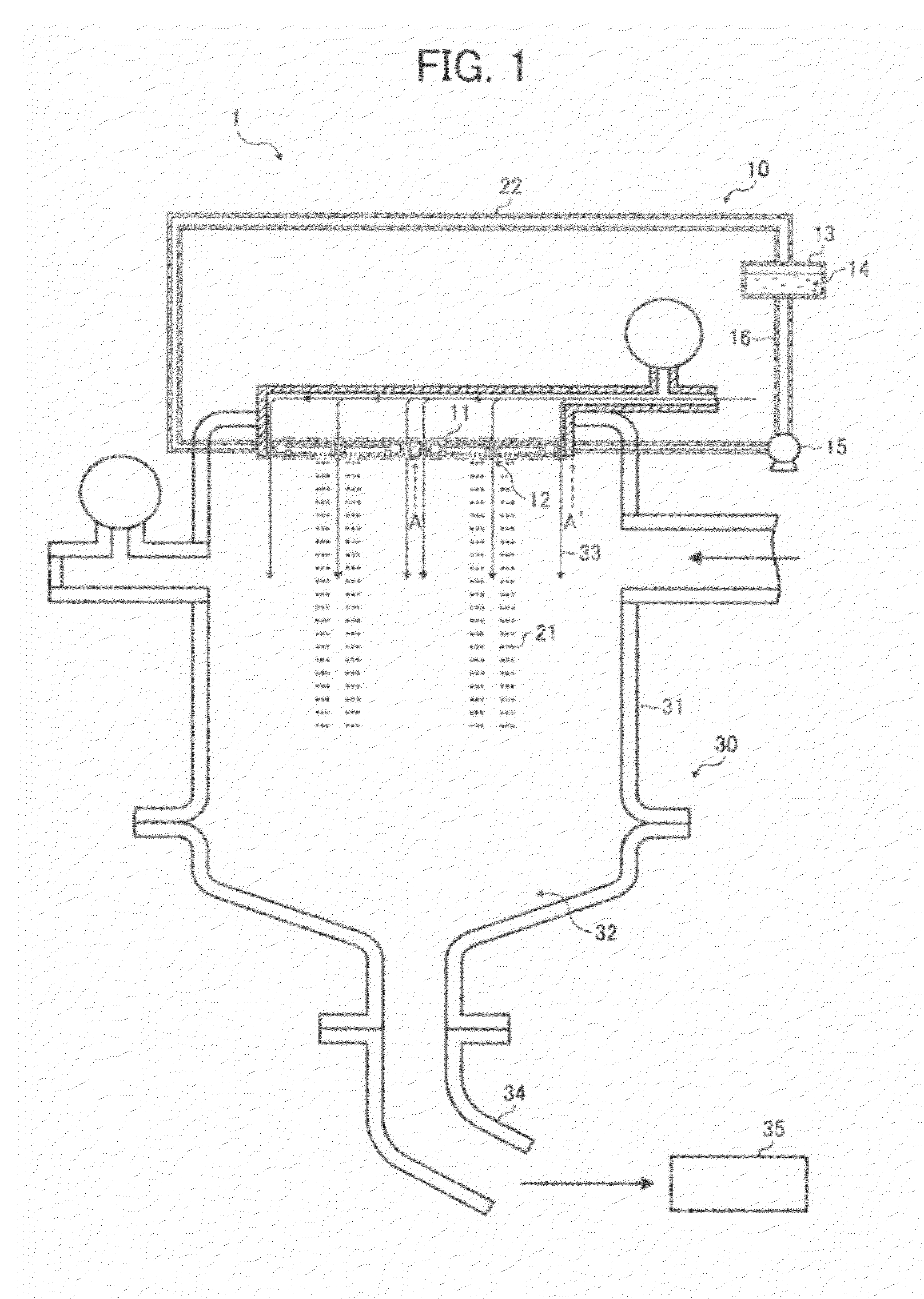
[0011]FIG. 2 is a cross-sectional view illustrating a liquid droplet
discharge head in a liquid droplet forming unit illustrated in FIG. 1;
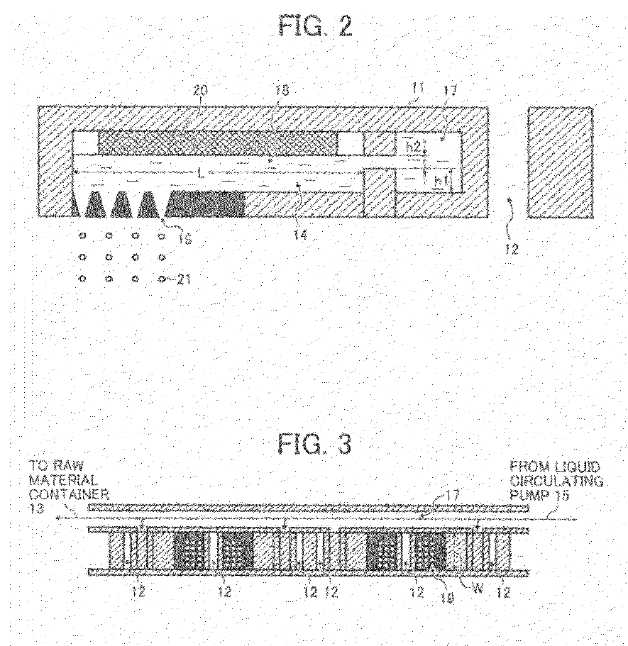
[0012]FIG. 3 is a cross-sectional view illustrating the liquid droplet forming unit viewed from the line A-A′ in FIG. 1;
[0013]FIG. 4A is a
schematic view illustrating the liquid droplet
discharge head 11 and FIG. 4B is a magnified view of the area circled by a dotted line in FIG. 4A;
[0014]FIG. 5 is a
schematic view illustrating the occurrence of vertical coalescence of liquid droplets;
[0015]FIGS. 6A to 6D show wave configurations (i.e., resonant
modes) of velocity and pressure standing
waves when N is 1, 2, or 3;
[0016]FIGS. 7A to 7C show wave configurations (i.e., resonant
modes) of velocity and pressure standing
waves when N is 4 or 5;
[0017]FIGS. 8A to 8E represent temporary variations in velocity and pressure distributions in the
liquid column resonance liquid chamber;
[0018]FIG. 9 shows an image of liquid droplet
discharge obtained by a
laser shadowgraph method;
[0019]FIG. 10 shows relations between drive frequency and discharge velocity;
[0020]FIG. 11 shows relations between applied
voltage and discharge velocity; and
[0021]FIG. 12 shows relations between applied
voltage and liquid droplet
diameter.
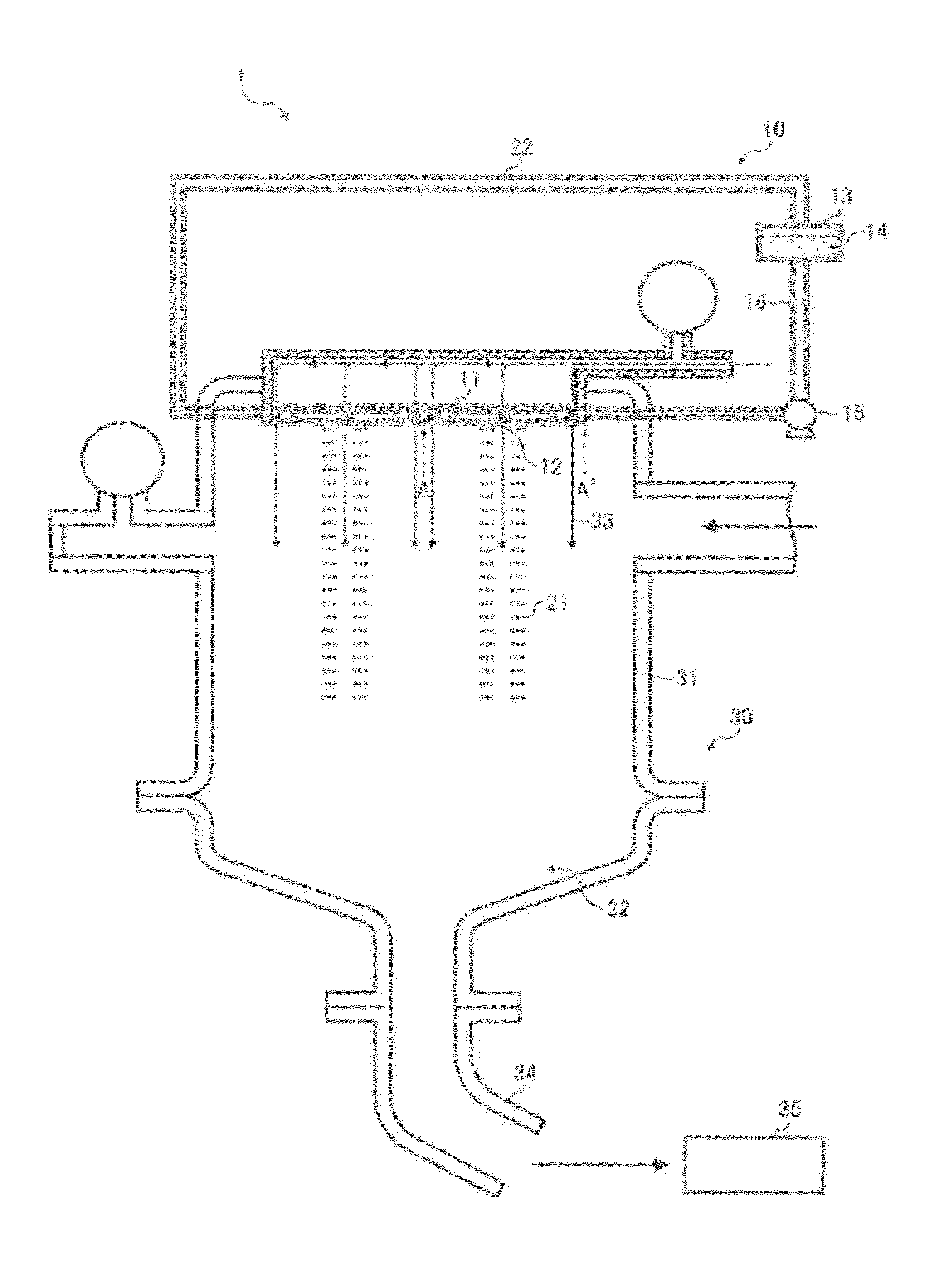
[0022]FIG. 1 is a schematic view illustrating a toner manufacturing apparatus according to exemplary embodiments of the invention. FIG. 2 is a cross-sectional view illustrating a liquid droplet discharge head in a liquid droplet forming unit illustrated in FIG. 1. FIG. 3 is a cross-sectional view illustrating the liquid droplet forming unit viewed from the line A-A′ in FIG. 1. A toner manufacturing apparatus 1 illustrated in FIG. 1 has a liquid droplet forming unit 10 and a
drying collecting unit 30. The liquid droplet forming unit 10 has a liquid chamber that is communicated with exterior through nozzles. The liquid droplet forming unit 10 has multiple liquid droplet discharge heads 11 that discharge a toner constituents liquid from a
liquid column resonance liquid chamber, to be described in detail later, through the nozzles to form the toner constituents liquid into liquid droplets. On both sides of each liquid droplet discharge head 11,
airflow pathways 12 through which an
airflow generated from an
airflow generator passes are provided so that the liquid droplets are guided to the
drying collecting unit 30. The liquid droplet forming unit 10 also has a
raw material container 13 that contains a toner constituents liquid 14, and a liquid
circulating pump 15 that supplies the toner constituents liquid 14 from the
raw material container 13 to a liquid common supply path 17 through a liquid supply
pipe 16 and returns the toner constituents liquid 14 from the liquid supply
pipe 16 to the
raw material container 13 through a liquid return
pipe 22. As illustrated in FIG. 2, the liquid droplet discharge head 11 has the liquid common supply path 17 and the
liquid column resonance liquid chamber 18. The liquid column resonance liquid chamber 18 is communicated with the liquid common supply path 17 provided on its one longitudinal end wall surface. The liquid column resonance liquid chamber 18 also has nozzles 19 that discharge toner liquid droplets 21 and a vibration generator 20 that generates high-frequency vibration so that a
standing wave occurs in liquid column resonance. The nozzles 19 are provided on one wall surface of the liquid column resonance liquid chamber 18 which is connected with both longitudinal end wall surfaces. The vibration generator 20 is connected to a high-frequency power source, not shown.
[0023]The
drying collecting unit 30 has a chamber 31 and a toner collecting part 32. Within the chamber 31, an
air current generated from an
air current generator, not shown, and a descending
air current 33 join together and form a large descending air current. The toner liquid droplets 21 discharged from the liquid droplet discharge heads 11 are conveyed downward not only by gravity but also by the descending air current 33. Thus, the toner liquid droplets 21 are prevented from decelerating by air resistance. Even when toner liquid droplets 21 are continuously discharged, they are prevented from decelerating by air resistance. Therefore, subsequent liquid droplets are prevented from catching up and coalescing with the preceding liquid droplets. The air current may be generated by either providing an
air blower upstream from the chamber 31 to apply pressure to the chamber 31 or sucking the chamber 31 from the toner collecting part 32 to reduce pressure in the chamber 31. Within the toner collecting part 32, a rotating air
current generator, not shown, is provided. The rotating air
current generator generates a rotating air current rotatable around an axis parallel to the vertical direction. The chamber 31 is connected to a toner retention part 35 that retains dried and solidified toner particles collected through a toner collecting tube 34.
[0024]The toner manufacturing apparatus 1 may operate as follows. Referring to FIG. 1, the liquid
circulating pump 15 supplies the toner constituents liquid 14 from the raw material container 13 to the liquid supply pipe 16. The toner constituents liquid 14 then flows into the liquid common supply path 17, as illustrated in FIG. 3, and is further supplied to the liquid column resonance liquid chamber 18 provided in the liquid droplet discharge head 11, as illustrated in FIG. 2. Within the liquid column resonance liquid chamber 18 filled with the toner constituents liquid 14, the vibration generator 20 causes liquid column resonance and a pressure
standing wave therein, i.e., a pressure distribution is formed. The toner liquid droplets 21 are discharged from the nozzles 19 provided on an area including antinodes of the pressure
standing wave generated in liquid column resonance. At the antinodes of the pressure standing wave, the amplitude in pressure variation is large enough to discharge the toner liquid droplets 21. Each antinode of the pressure standing wave (i.e., node of a velocity standing wave) is defined as a region extending from a position at a local
maximum amplitude toward a position at a local minimum amplitude for a distance ±⅔ of the
wavelength, preferably ±¼ of the
wavelength. At the antinodes of the pressure standing wave, each of the multiple nozzles 19 uniformly discharges toner liquid droplets at a high efficiency without causing
nozzle clogging. After passing the liquid common supply path 17, the toner constituents liquid 14 flows into the liquid return pipe 22 and returns to the raw material container 13. Because the amount of the toner constituents liquid 14 in the liquid column resonance liquid chamber 18 is reduced after the toner liquid droplets 21 have been discharged,
suction force generated by the action of the standing
waves occurred in liquid column resonance is reduced within the liquid column resonance liquid chamber 18. Thus, the liquid common supply path 17 temporarily increases the flow rate of the toner constituents liquid 14 to fill the liquid column resonance liquid chamber 18 with the toner constituents liquid 14. After the liquid column resonance liquid chamber 18 has been refilled with the toner constituents liquid 14, the flow rate of the toner constituents liquid 14 in the liquid common supply path 17 is returned. Thus, the toner constituents liquid 14 starts circulating through the liquid supply pipe 16 and the liquid return pipe 22 again. The toner liquid droplets 21 discharged from the liquid droplet discharge heads 11 are conveyed downward not only by gravity but also by the descending air current 33 formed from an air current generated from the air
current generator, not shown, that passes through the airflow pathways 12, as illustrated in FIG. 1. A rotating air current generated from the rotating air current generator, not shown, and the descending air current 33 form a spiral air current along a conical inner wall surface of the toner collecting part 32. The spiral air current dries and solidifies the toner liquid droplets 21 into toner particles. The toner particles thus formed are retained in the toner retention part 35 through the toner collecting tube 34.
[0025]The liquid column resonance liquid chamber 18 is formed by jointing frames. The frames are formed from a material having a
high stiffness which does not adversely affect liquid resonant frequency at drive frequency, such as a
metal,
ceramic, and
silicon. Referring to FIG. 2, a length L between both longitudinal ends of the liquid column resonance liquid chamber 18 is determined based on a liquid column resonance principle to be described in detail later. Referring to FIG. 3, a width W of the liquid column resonance liquid chamber 18 is preferably smaller than half of the length L so as not to give excessive frequency to the liquid column resonance. To drastically improve manufacturability, the liquid droplet forming unit 10 preferably includes multiple liquid column resonance liquid chambers 18. The number of the liquid column resonance liquid chambers 18 in one liquid droplet forming unit 10 is preferably 100 to 2,000 from the viewpoint of
operability and manufacturability. The liquid common supply path 17 is communicated with the multiple liquid column resonance liquid chambers 18 so that the toner constituents liquid 14 is supplied to each liquid column resonance liquid chamber 18.
[0026]The vibration generator 20 is driven at a predetermined frequency. Preferably, the vibration generator 20 is formed from a piezoelectric body and an elastic plate attached to each other. The elastic plate constitutes a part of the wall of the liquid column resonance liquid chamber 18 so that the piezoelectric body does not contact the liquid. The piezoelectric body may be, for example, a piezoelectric
ceramic such as
lead zirconate titanate (PZT). Because of having a small displacement, the piezoelectric body is generally laminated. Additionally, piezoelectric polymers such as
polyvinylidene fluoride (PVDF), crystals, and single crystals of LiNbO3, LiTaO3, and KNbO3 are also
usable. Preferably, the vibration generator 20 in each liquid column resonance liquid chamber 18 is independently controllable. Alternatively, a single blockish vibrating material may be partially
cut to fit the arrangement of the liquid column resonance liquid chambers 18. In this case, preferably, each liquid column resonance liquid chamber 18 is independently controllable through the elastic plate.
[0027]Each of the nozzles 19 preferably has an outlet
diameter of 1 to 40 μm. When the outlet diameter is less than 1 μm, the resulting liquid droplets may be too small to be used as toner particles. Moreover, in a case in which the toner constituents liquid includes
solid particles such as pigments, the nozzles 19 may be frequently clogged. When the outlet diameter is greater than 40 μm, the resulting liquid droplets may be relatively large. They are dried and solidified into toner particles having a particle diameter of 3 to 6 μm. In some of these cases, the toner constituents liquid needs to be diluted with an
organic solvent and therefore a large amount of drying energy is required to obtain toner particles, which is undesirable. It is preferable to provide a large number of nozzles 19 in the width direction of the liquid column resonance liquid chamber 18, as illustrated in FIG. 3, to improve production efficiency. The liquid column resonant frequency depends on the arrangement of the nozzles 19. Thus, the liquid column resonant frequency is preferably determined based on discharge condition of liquid droplets.
[0028]To prevent coalescence of liquid droplets, an interval p between adjacent nozzles 19 is preferably 6 to 160 μm. When the interval p is too small or large, liquid droplets discharged from adjacent nozzles 19 are so close to each other that they may laterally coalesce. This phenomenon in which liquid droplets get coalesced with those discharged from an adjacent
nozzle 19 is hereinafter referred to as lateral coalescence. The ratio p / d of the interval p to the outlet diameter d of the nozzles 19 is between 2.5 and 7.5. FIG. 4A is a schematic view illustrating the liquid droplet discharge head 11 and FIG. 4B is a magnified view of the area circled by a dotted line in FIG. 4A. When p, d and p / d are within the above-described ranges, no coalescence occurs, as illustrated in FIG. 4B, because accompanying air currents formed around adjacent liquid droplets are overlapped with each other. When p, d and p / d are beyond the above-described ranges, vertical coalescence occurs at about 2 to 5 mm below the nozzles 19, as illustrated in FIG. 5. This is because accompanying air currents formed around adjacent liquid droplets are not sufficiently overlapped with each other, and therefore the liquid droplets are decelerated. The interval p between adjacent nozzles 19 is defined as a
minimum distance between certain points on the circumferences of adjacent nozzles 19, as is shown in FIG. 4B. Not all the nozzles 19 are necessarily in the above conditions but at least a pair of nozzles 19 is in the above conditions so that accompanying air currents formed around adjacent liquid droplets are overlapped with each other. Multiple pairs of nozzles 19 in the above conditions may be distributed over the entire region of the liquid droplet discharge head 11.
[0029]A mechanism of liquid droplet formation in the liquid droplet forming unit 10 is described in detail below. First, a mechanism of liquid column resonance in the liquid column resonance liquid chamber 18 is described referring to FIG. 2. The resonant
wavelength λ is represented by the following formula (1):
[0030]wherein c represents a sonic speed in the toner constituents liquid in the liquid column resonance liquid chamber 18 and f represents a drive frequency given to the toner constituents liquid from the vibration generator 20.
[0031]In FIG. 2, L represents a length between the fixed end of the frame of the liquid column resonance liquid chamber 18 and the other end thereof closer to the liquid common supply path 17; h1 (about 80 μm) represents a height of the end of the frame of the liquid column resonance liquid chamber 18 closer to the liquid common supply path 17; and h2 (about 40 μm) represents a height of a communication opening between the liquid column resonance liquid chamber 18 and the liquid common supply path 17. Here, h1 is twice as much as h2. When both ends are fixed (i.e., closed), resonance most effectively occurs when the length L is an even multiple of λ / 4. In this case, the length L is represented by the following formula (2):
[0032]The formula (2) is also satisfied when both ends are open. Similarly, when one end is open (so that pressure can be released) and the other end is closed (i.e., fixed), resonance most effectively occurs when the length L is an odd multiple of λ / 4. In this case, the length L is represented by the formula (2) as well, wherein N represents an odd number.
[0033]Thus, the most effective drive frequency f is derived from the formulae (1) and (2) and represented by the following formula (3):
[0034]Actually, vibration is not infinitely amplified because the liquid attenuates resonance due to its
viscosity. Therefore, resonance can occur even at a frequency around the most effective drive frequency f represented by the formula (3).
[0035]FIGS. 6A to 6D show wave configurations (i.e., resonant
modes) of velocity and pressure standing waves when N is 1, 2, or 3. FIGS. 7A to 7C show wave configurations (i.e., resonant modes) of velocity and pressure standing waves when N is 4 or 5. The standing waves are longitudinal waves in actuality, but are generally illustrated as shown in FIGS. 6A to 6D and FIGS. 7A to 7C. In FIGS. 6A to 6D and FIGS. 7A to 7C,
solid lines represent velocity standing waves and dotted lines represent pressure standing waves. Referring to FIG. 6A, when one end is closed and N is 1, amplitude of the velocity standing wave is zero at the closed end and is maximum at the open end. When the length between both longitudinal ends of the liquid column resonance liquid chamber 18 is L and the resonant wavelength of the liquid is λ, standing waves most effectively occur when N is an integer of 1 to 5. Wave configurations of the standing waves depend on whether either end is open or closed. Whether either end is open or closed depends on conditions of nozzles and / or supply openings. In
acoustics, a closed end is defined as a point at which longitudinal velocity of a medium (e.g., a liquid) is zero and pressure thereof is maximum. An open end is defined as a point at which pressure of the medium is zero. The closed end is acoustically considered as a hard wall that reflects waves. Resonant standing waves as illustrated in FIGS. 6A to 6D and FIGS. 7A to 7C occur when each end is ideally completely closed or open. Configurations of standing waves vary depending on the number and / or arrangement of the nozzles. Thus, resonant frequency can appear even at a position displaced from the position derived from the formula (3). Thus, stable discharge conditions can be created by adjusting the drive frequency. For example, when the sonic speed c in the liquid is 1,200 m / s, the length L between both ends of the liquid column resonance liquid chamber 18 is 1.85 mm, both ends are fixed with wall surfaces, i.e., both ends are closed, and N is 2, the most effective resonant frequency is derived from the formula (3) as 324 kHz. For another example, when the sonic speed c in the liquid is 1,200 m / s, the length L between both ends of the liquid column resonance liquid chamber 18 is 1.85 mm, both ends are fixed with wall surfaces, i.e., both ends are closed, and N is 4, the most effective resonant frequency is derived from the formula (3) as 648 kHz. Higher resonance can occur in the same liquid column resonance liquid chamber 18.
[0036]To increase frequency, preferably, both ends of the liquid column resonance liquid chamber 18 are equivalent to closed ends or are regarded as acoustically soft walls under the influence of the nozzle openings. Of course, both ends may be equivalent to open ends. The influence of the nozzle openings means a lesser
acoustic impedance and a greater compliance component. Preferably, the liquid column resonance liquid chamber 18 has wall surfaces on both longitudinal ends, as illustrated in FIG. 6B and FIG. 7A, because all possible resonant modes are available as if both ends are closed or one end is open.
[0037]The drive frequency depends on the number, arrangement, and cross-sectional shape of the nozzles 19. For example, as the number of the nozzles 19 increases, closed ends of the liquid column resonance liquid chamber 18 are gradually released from restriction. As a result, a resonant standing wave is generated as if both ends are substantially open, and the drive frequency is increased. The restriction releases from the position of the nozzle 19 provided closest to the liquid supply path 17. Actually, the cross-sectional shape of each nozzle 19 may be a round shape or the volume of each nozzle 19 may vary depending on the frame thickness. Thus, the actual standing wave has a shorter wavelength and a higher frequency than the drive frequency. Upon application of a
voltage to the vibration generator 20 with the drive frequency thus determined, the vibration generator 20 deforms so as to generate a resonant standing wave most effectively. A liquid column resonant standing wave can generate even at a frequency around the most effective drive frequency for generating a resonant standing wave. When the vibration generator 20 vibrates at a drive frequency f satisfying the following formulae (4) and (5), a liquid column resonance is generated and liquid droplets are discharged from the nozzles 19: wherein L represents a length between both longitudinal ends of the liquid column resonance liquid chamber 18 and Le represents a distance between a longitudinal end of the liquid column resonance liquid chamber 18 on which a liquid common supply path 17 is provided and the nozzle 19 closest to the longitudinal end.
[0013]FIG. 4A is a schematic view illustrating the liquid droplet discharge head 11 and FIG. 4B is a magnified view of the area circled by a dotted line in FIG. 4A;
[0039]According to the above-described principle of liquid column resonance, a pressure standing wave is formed in the liquid column resonance liquid chamber 18 and liquid droplets are continuously discharged from the nozzles 19 provided on a part of the liquid column resonance liquid chamber 18 as illustrated in FIG. 2. When the nozzles 19 are provided at a position of the
maximum amplitude of the pressure standing wave,
discharge efficiency becomes maximum, which allows low-voltage driving. In terms of productivity, more than one nozzles 19 are preferably provided. In particular, the number of the nozzles 19 is preferably 2 to 100. When the number of the nozzles 19 is too large, the vibration generator 20 requires a higher voltage in forming desired-size liquid droplets, resulting in unstable behavior of the piezoelectric body as the vibration generator 20. To prevent coalescence of liquid droplets, the interval between the nozzles 19 is preferably 6 μm to 160 μm.
[0040]Details of liquid column resonance generated in the liquid column resonance liquid chamber 18 are described with reference to FIGS. 8A to 8E. In FIGS. 8A to 8E,
solid lines represent velocity distributions at arbitrary points within the liquid column resonance liquid chamber 18. With respect to velocity, the direction from the liquid common supply path 17 side toward the liquid column resonance liquid chamber 18 is defined as the plus (+) direction and the opposite direction is defined as the minus (−) direction. Dotted lines represent pressure distributions at arbitrary points within the liquid column resonance liquid chamber 18. A positive (+) pressure and a negative (−) pressure relative to
atmospheric pressure respectively create downward and upward pressures in FIGS. 8A to 8E. In FIGS. 8A to 8E, a height (equivalent to h1 in FIG. 2) of the end of the frame of the liquid column resonance liquid chamber 18 closer to the liquid common supply path 17 is twice as much as a height (equivalent to h2 in FIG. 2) of the communication opening between the liquid column resonance liquid chamber 18 and the liquid common supply path 17. FIGS. 8A to 8E represent temporary variations in velocity and pressure distributions under the assumption that both ends of the liquid column resonance liquid chamber 18 are approximately closed.
[0041]FIG. 8A shows pressure and velocity wave configurations within the liquid column resonance liquid chamber 18 when liquid droplets are being discharged. FIG. 8B shows that
meniscus pressure gradually increases again immediately after liquid droplets have been discharged and the liquid has drawn back. In FIGS. 8A and 8B, the pressure within the liquid column resonance liquid chamber 18 becomes maximum at the position where the nozzles 19 are provided. Thereafter, as illustrated in FIG. 8C, the
positive pressure around the nozzles 19 decreases toward negative pressures so as to start discharging liquid droplets 21.
[0042]Thereafter, as illustrated in FIG. 8D, when the pressure around the nozzles 19 becomes minimum, the toner constituents liquid 14 starts filling the liquid column resonance liquid chamber 18. Thereafter, as illustrated in FIG. 8E, the negative pressure around the nozzles 19 increases toward positive pressures. Thus, the toner constituents liquid 14 stops filling the liquid column resonance liquid chamber 18. Thereafter, as illustrated in FIG. 8A, the pressure within the liquid column resonance liquid chamber 18 becomes maximum again at the position where the nozzles 19 are provided so as to start discharging liquid droplets 21 again. In summary, a standing wave is generated in liquid column resonance caused by a high-frequency driving of the generation vibrator 20 within the liquid column resonance liquid chamber 18. The nozzles 19 are provided to the position corresponding to antinodes of the standing wave at which the
pressure amplitude becomes maximum. Thus, toner liquid droplets 21 are continuously discharged from the nozzles 19 in accordance with the cycle of the antinodes.
[0043]An exemplary embodiment that causes liquid droplet discharge by the principle of liquid column resonance is described in detail below. In the present embodiment, referring to FIG. 2, the length L between both longitudinal ends of the liquid column resonance liquid chamber 18 is 1.85 mm and the resonant mode N is 2. The first to fourth nozzles are provided to the position corresponding to antinodes of the pressure standing wave. FIG. 9 shows an image of liquid droplet discharge obtained by a
laser shadowgraph method when the discharge is caused by a
sine wave having a drive frequency of 340 kHz. It is clear from FIG. 9 that the discharged liquid droplets are very uniform in both particle size and discharge velocity. FIG. 10 shows relations between drive frequency and discharge velocity when the liquid droplet discharge is caused by sine waves having a driving frequency between 290 and 395 kHz with the same amplitude. It is clear from FIG. 10 that the discharge velocity becomes maximum and uniform when the drive frequency is around 340 kHz in all the first to fourth nozzles. Accordingly, it is clear that the liquid droplet discharge is caused at the position corresponding to antinodes of the standing wave generated in liquid column resonance having a frequency of 340 kHz, which is the second resonant mode. It is also clear from FIG. 10 that liquid droplet discharge is not caused between drive frequencies of 130 kHz (i.e., the first resonant mode) and 340 kHz (i.e., the second resonant mode), at which the discharge velocity becomes local maximum. This clearly indicates generation of standing wave in liquid column resonance.
[0044]FIG. 11 shows relations between applied voltage and discharge velocity. FIG. 12 shows relations between applied voltage and liquid droplet diameter. It is clear from FIGS. 11 and 12 that both discharge velocity and liquid droplet diameter monotonically increase as applied voltage increases. Thus, both discharge velocity and liquid droplet diameter can be arbitrarily adjusted by controlling the applied voltage.
[0045]The following examples show toner manufacturing apparatuses according to exemplary embodiments of the invention. They show relations between standing waves and the number, pattern, and arrangement of the nozzles. These examples are provided herein for the purpose of illustration only and are not intended to be limiting. In the descriptions in the following examples, the numbers represent weight ratios in parts, unless otherwise specified. In the following examples, resonant frequency can be determined by experimentally varying discharge frequency. The examples also include evaluation results of toners obtained with the toner manufacturing apparatuses.
[0046]In Example 1, the liquid droplet discharge head 11 illustrated in FIG. 2 was used. A standing wave with the resonant mode N of 2 was generated while fixing both ends. The drive frequency was 328 kHz, which was a resonant peak frequency. The resonant peak frequency is a frequency at which discharge velocity becomes maximum, which can be experimentally determined from a graph as shown in FIG. 8. The resonant peak frequency is generally obtained at a node of a velocity standing wave and an antinode of a pressure standing wave generated in liquid column resonance, at which pressure becomes maximum.
[0049]A toner constituents liquid was prepared by uniformly mixing 100 parts of a
polyester resin (i.e., a binder resin), 30 parts of the colorant dispersion, 30 parts of the
wax dispersion, and 840 parts of
ethyl acetate for 10 minutes using a mixer having agitation blades. Neither the colorant particles nor the
wax particles aggregated due to
solvent shock.
[0047]First, 17 parts of a
carbon black (REGAL 400 from Cabot Corporation), 3 parts of a colorant dispersant (AJISPER PB821 from Ajinomoto Fine-Techno Co., Inc.), and 80 parts of
ethyl acetate were mixed with a mixer having agitation blades. Thus, a primary colorant dispersion was prepared. The primary colorant dispersion was further dispersed with strong shearing force using a DYNOMILL to completely remove aggregations having a size greater than 5 μm. Thus, a colorant dispersion was prepared.
[0049]A toner constituents liquid was prepared by uniformly mixing 100 parts of a
polyester resin (i.e., a binder resin), 30 parts of the colorant dispersion, 30 parts of the wax dispersion, and 840 parts of ethyl acetate for 10 minutes using a mixer having agitation blades. Neither the colorant particles nor the wax particles aggregated due to
solvent shock.
[0079]The toner is prepared by dissolving or dispersing toner constituents, such as a binder resin, a colorant, and a
release agent, to prepare a toner constituents liquid, forming the toner constituents liquid into liquid droplets, and drying and solidifying the liquid droplets into toner particles.
[0050]The toner constituents liquid thus prepared was set to the toner manufacturing apparatus illustrated in FIG. 1 having the liquid droplet discharge head 11 illustrated in FIG. 2. The toner constituents liquid was formed into liquid droplets under the following conditions, and the liquid droplets were dried and solidified into mother toner particles.
[0051]Length of liquid column resonance liquid chamber: 1.85 mm
[0058]Peak vale of applied voltage
sine wave: 10.0 V
[0059]The dried and solidified mother toner particles were exposed to soft X-
ray to be electrically neutralized, and then collected by suction with a filter having pores of 1 μm. The collected mother toner particles were subjected to a measurement of
particle size distribution with a flow particle image analyzer (FPIA-2000 from Sysmex Corporation). As a result, the mother toner particles had a weight average particle diameter (D4) of 5.5 μm and a number average particle diameter (Dn) of 5.0 μm. The
particle size distribution (D4 / Dn) was 1.10.
[0060]An exemplary measurement procedure using FPIA-2000 is described below. First, several drops of a
nonionic surfactant (preferably CONTAMINON N from Wako Pure Chemical Industries, Ltd.) are added to 10 ml of water from which fine foreign substances have been previously removed by a filter. The water is containing particles having a circle-equivalent diameter which falls within the measuring range (e.g., 0.60 to 159.21 μm) in a number only 20 or less per 10−3 cm3. After adding 5 mg of a sample, the resulting liquid is subjected to a dispersion treatment for 1 minute using an ultrasonic
disperser UH-50 from STM at 20 kHz and 50 W / 10 cm3. The liquid is subjected to this dispersion treatment for 5 minutes in total. The resulting sample dispersion is containing 4,000 to 8,000 particles per 10−3 cm3, the particles having a circle-equivalent diameter which falls within the measuring range of not less than 0.60 μm and less than 159.21 μm.
[0061]The sample dispersion is passed through a flow path of a flat transparent
flow cell having a thickness of about 200 μm. A stroboscopic lamp and a
CCD camera are respectively provided on opposite sides of the
flow cell so that an
optical path is formed crossing the thickness direction of the
flow cell. While the sample dispersion is flowing, the stroboscopic lamp emits light at an interval of 1 / 30 seconds to obtain a two-dimensional image of the particles flowing in the flow
cell. The image is parallel to a part of the flow
cell. Circle-equivalent diameter of each particle is calculated as a circle having the same area as the two-dimensional image of the particle.
[0062]More than 1,200 particles can be subjected to the measurement of circle-equivalent diameter in about 1 minute. Thus, a number distribution and a ratio (% by number) of particles having a specific circle-equivalent diameter can be determined. In the resulting frequency and cumulative distributions (%), a range of 0.06 to 400 μm is divided into 226 channels (i.e., 1
octave is divided into 30 channels). The actual measuring range is not less than 0.60 μm and less than 159.21 μm.
[0063]After being collected by
cyclone, the dried and solidified mother toner particles were mixed with 1.0% of a hydrophobized silica (H2000 from Clariant Japan K.K.) using a HENSCHEL MIXER (from Mitsui Mining Co., Ltd.). Thus, a toner was prepared.
[0064]A
coating layer dispersion in which a
silicone resin was dispersed in
toluene was spray-coated on a core material (i.e., a spherical ferrite particle having an average particle diameter of 50 μm), followed by burning and cooling. Thus, a carrier having a
coating layer having an average thickness of 0.2 μm was prepared.
[0065]A two-component developer was prepared by mixing 4 parts of the toner and 96 parts of the carrier.
[0066]The above-prepared developer was set in a commercially-available copier (IMAGIO NEO 271 from Ricoh Co., Ltd.) and a running test was performed. In the running test, an image having an image occupancy of 7% was continuously printed on a paper TYPE 6000 (from Ricoh Co., Ltd.). The 10th image (i.e., an initial image) and the 30,000th image were visually observed with an
optical microscope at a
magnification of 1,000,000 to evaluate
thin line reproducibility to be graded on a 4-point scale (A, B, C, and D). A is the best and D is the worst. The grade D is not suitable for practical use. The evaluation results are shown in Table 1. In Example 1, neither vertical nor lateral coalescence occurred and
thin line reproducibility was very good.
[0067]The procedure in Example 1 is repeated except for changing the
peak value of the applied voltage
sine wave to 8 V, the interval between nozzles to 30 μm, and the diameter of nozzles to 6.0 μm. The obtained toner has a number average particle diameter (Dn) of 4.2 μm and the
particle size distribution D4 / Dn is 1.08. In Example 2, p / d is 5. In Example 2, neither vertical nor lateral coalescence occur and
thin line reproducibility is very good.
[0012]FIG. 3 is a cross-sectional view illustrating the liquid droplet forming unit viewed from the line A-A′ in FIG. 1;
[0068]The procedure in Example 1 is repeated except for changing the
peak value of the applied voltage sine wave to 11 V, the interval between nozzles to 75 μm, and the diameter of nozzles to 10.0 μm. The obtained toner has a number average particle diameter (Dn) of 5.8 μm and the particle size distribution D4 / Dn is 1.18. In Example 3, p / d is 7.5. In Example 3, neither vertical nor lateral coalescence occur and thin line reproducibility is good.
[0069]The procedure in Example 1 is repeated except for changing the
peak value of the applied voltage sine wave to 13 V, the interval between nozzles to 75 μm, and the diameter of nozzles to 12.0 μm. The obtained toner has a number average particle diameter (Dn) of 5.7 μm and the particle size distribution D4 / Dn is 1.05. In Example 4, p / d is 2.5. In Example 4, neither vertical nor lateral coalescence occur and thin line reproducibility is good.
[0014]FIG. 5 is a schematic view illustrating the occurrence of vertical coalescence of liquid droplets;
[0070]The procedure in Example 1 is repeated except for changing the peak value of the applied voltage sine wave to 10 V, the interval between nozzles to 20 μm, and the diameter of nozzles to 8.0 μm. The cross-sectional shape of the nozzle is straight. The obtained toner has a number average particle diameter (Dn) of 5.1 μm and the particle size distribution D4 / Dn is 1.06. In Example 5, p / d is 2.5. In Example 5, neither vertical nor lateral coalescence occur and thin line reproducibility is good.
[0071]The procedure in Example 1 is repeated except for changing the peak value of the applied voltage sine wave to 10 V, the interval between nozzles to 20 μm, and the diameter of nozzles to 4.2 μm. The cross-sectional shape of the nozzle is straight. The obtained toner has a number average particle diameter (Dn) of 3.95 μm and the particle size distribution D4 / Dn is 1.10. In Example 6, p / d is 4.75. In Example 6, neither vertical nor lateral coalescence occur and thin line reproducibility is good.
[0072]The procedure in Example 1 is repeated except for changing the peak value of the applied voltage sine wave to 10 V, the interval between nozzles to 30 μm, and the diameter of nozzles to 4.2 μm. The cross-sectional shape of the nozzle is straight. The obtained toner has a number average particle diameter (Dn) of 4.0 μm and the particle size distribution D4 / Dn is 1.06. In Example 7, p / d is 7.14. In Example 7, neither vertical nor lateral coalescence occur and thin line reproducibility is good.
[0017]FIGS. 8A to 8E represent temporary variations in velocity and pressure distributions in the liquid column resonance liquid chamber;
[0073]The procedure in Example 1 is repeated except for changing the peak value of the applied voltage sine wave to 9.0 V, the interval between nozzles to 40 μm, and the diameter of nozzles to 14.8 μm. The cross-sectional shape of the nozzle is straight. The obtained toner has a number average particle diameter (Dn) of 6.8 μm and the particle size distribution D4 / Dn is 1.09. In Example 8, p / d is 2.7. In Example 8, neither vertical nor lateral coalescence occur and thin line reproducibility is good.
[0018]FIG. 9 shows an image of liquid droplet discharge obtained by a
laser shadowgraph method;
[0072]The procedure in Example 1 is repeated except for changing the peak value of the applied voltage sine wave to 10 V, the interval between nozzles to 30 μm, and the diameter of nozzles to 4.2 μm. The cross-sectional shape of the nozzle is straight. The obtained toner has a number average particle diameter (Dn) of 4.0 μm and the particle size distribution D4 / Dn is 1.06. In Example 7, p / d is 7.14. In Example 7, neither vertical nor lateral coalescence occur and thin line reproducibility is good.
[0075]The procedure in Example 1 was repeated except for changing the interval between nozzles to 6 μm. The obtained toner had a number average particle diameter (Dn) of 8.2 μm and the particle size distribution D4 / Dn was 1.8. In Comparative Example 1, liquid droplets discharged from adjacent nozzles were laterally coalesced and a part of the liquid droplets were further vertically coalesced.
[0076]The procedure in Example 1 is repeated except for changing the interval between nozzles to 100 μm and the diameter of nozzles to 10.0 μm. The obtained toner has a number average particle diameter (Dn) of 6.2 μm and the particle size distribution D4 / Dn is 1.4. In Comparative Example 2, liquid droplets discharged from the same nozzle are vertically coalesced with the one-cycle-preceding liquid droplets.
[0077]The toner according to exemplary aspects of the invention may be obtained by the toner manufacturing apparatus according to exemplary aspects of the invention. The toner is substantially monodisperse.
[0078]The particle size distribution (i.e., the ratio of weight average molecular weight to number average molecular weight) of the toner is preferably 1.00 to 1.15, and more preferably 1.00 to 1.05. The weight average particle diameter of the toner is preferably 1 to 20 μm, and more preferably 3 to 10 μm.
[0079]The toner is prepared by dissolving or dispersing toner constituents, such as a binder resin, a colorant, and a
release agent, to prepare a toner constituents liquid, forming the toner constituents liquid into liquid droplets, and drying and solidifying the liquid droplets into toner particles.
[0080]The toner constituents include a binder resin, a colorant, and a wax. The toner constituents may further include other materials such as a charge controlling agent, if needed.
[0093]The
polyester polymers may be formed from an
alcohol and a
carboxylic acid. Specific examples of suitable
divalent alcohols for preparing the polyester
polymer include, but are not limited to,
ethylene glycol,
propylene glycol, 1,3-
butanediol, 1,4-
butanediol, 2,3-
butanediol,
diethylene glycol,
triethylene glycol, 1,5-pentanediol, 1,6-hexanediol,
neopentyl glycol, 2-ethyl-1,3-hexanediol, hydrogenated
bisphenol A, and diols obtained from a reaction between a
cyclic ether (e.g.,
ethylene oxide,
propylene oxide) and
bisphenol A.
[0093]The polyester polymers may be formed from an
alcohol and a
carboxylic acid. Specific examples of suitable
divalent alcohols for preparing the polyester
polymer include, but are not limited to,
ethylene glycol,
propylene glycol, 1,3-butanediol, 1,4-butanediol, 2,3-butanediol,
diethylene glycol,
triethylene glycol, 1,5-pentanediol, 1,6-hexanediol,
neopentyl glycol, 2-ethyl-1,3-hexanediol, hydrogenated
bisphenol A, and diols obtained from a reaction between a
cyclic ether (e.g.,
ethylene oxide,
propylene oxide) and
bisphenol A.
[0083]Specific examples of the
acrylic monomers include, but are not limited to, acrylic acids and esters thereof such as
methyl acrylate,
ethyl acrylate, propyl
acrylate, n-
butyl acrylate, isobutyl
acrylate, n-
octyl acrylate, n-dodecyl
acrylate, 2-ethylhexyl acrylate, stearyl acrylate, 2-chloroethyl acrylate, and phenyl acrylate.
[0084]Specific examples of the
methacrylic monomers include, but are not limited to, methacrylic acids and esters thereof such as
methyl methacrylate, ethyl
methacrylate, propyl
methacrylate, n-
butyl methacrylate, isobutyl
methacrylate, n-octyl methacrylate, n-
dodecyl methacrylate, 2-ethylhexyl methacrylate, stearyl methacrylate, phenyl methacrylate, dimethylaminoethyl methacrylate, and
diethylaminoethyl methacrylate.
[0085]The vinyl homopolymers and copolymers may be formed from the following monomers (1) to (18). (1) Monoolefins, such as ethylene, propylene, butylene, and
isobutylene. (2) Polyenes, such as butadiene and
isoprene. (3) Vinyl halides, such as
vinyl chloride, vinylidene
chloride, vinyl
bromide, and
vinyl fluoride. (4) Vinyl esters, such as
vinyl acetate, vinyl
propionate, and vinyl benzoate. (5) Vinyl ethers, such as vinyl methyl
ether, vinyl ethyl
ether, and vinyl isobutyl
ether. (6) Vinyl ketones, such as vinyl
methyl ketone, vinyl hexyl
ketone, and methyl isopropenyl
ketone. (7) N-Vinyl compounds, such as N-vinyl
pyrrole, N-
vinyl carbazole, N-vinyl indole, and N-vinyl pyrrolidone. (8) Vinylnaphthalenes. (9)
Acrylic acid and
methacrylic acid derivatives, such as
acrylonitrile,
methacrylonitrile, and
acrylamide. (10) Unsaturated dibasic acids, such as
maleic acid,
citraconic acid,
itaconic acid, alkenyl
succinic acid,
fumaric acid, and mesaconic acid. (11) Unsaturated
dibasic acid anhydrides, such as
maleic acid anhydride,
citraconic acid anhydride,
itaconic acid anhydride, and alkenyl
succinic acid anhydride. (12) Monoesters of unsaturated dibasic acids, such as
maleic acid monomethyl ester, maleic acid monoethyl ester, maleic acid monobutyl ester,
citraconic acid monomethyl ester, citraconic acid monoethyl ester, citraconic acid monobutyl ester,
itaconic acid monomethyl ester, alkenyl
succinic acid monomethyl ester,
fumaric acid monomethyl ester, and mesaconic acid monomethyl ester. (13) Unsaturated
dibasic acid esters, such as dimethyl maleic acid and dimethyl
fumaric acid. (14) α,β-Unsaturated acids, such as
crotonic acid and
cinnamic acid. (15)4-Unsaturated acid anhydrides, such as
crotonic acid anhydride and
cinnamic acid anhydride. (16) Carboxyl-group-containing monomers, such as anhydrides between α,β-unsaturated acids and lower fatty acids; and alkenyl
malonic acid, alkenyl
glutaric acid, alkenyl
adipic acid, and anhydrides and monoesters thereof. (17) Hydroxyalkyl esters of acrylic acids and methacrylic acids, such as 2-hydroxyethyl acrylate, 2-
hydroxyethyl methacrylate, and 2-
hydroxypropyl methacrylate. (18) Hydroxyl-group-containing monomers, such as 4-(1-hydroxy-1-methylbutyl)
styrene and 4-(1-hydroxy-1-methyhexyl)
styrene.
[0090]The vinyl homopolymers and copolymers are obtained using a polymerization initiator. Specific examples of
usable polymerization initiators include, but are not limited to, 2,2′-
azobis isobutyronitrile, 2,2′-azobis(4-methoxy-2,4-dimethylvaleronitrile), 2,2′-azobis(2,4-dimethylvaleronitrile), 2,2′-azobis(2-methylbutyronitrile), dimethyl-2,2′-azobis isobutyrate, 1,1′-azobis(1-cyclohexanecarbonitrile), 2-(carbamoylazo)-isobutyronitrile, 2,2′-azobis(2,4,4-trimethylpentane), 2-phenylazo-2′,4′-dimethyl-4′-methoxyvaleronitrile, 2,2′-azobis(2-methylpropane),
ketone peroxides (e.g.,
methyl ethyl ketone peroxide, acetyl
acetone peroxide,
cyclohexanone peroxide), 2,2-bis(tert-butylperoxy)
butane, tert-butyl hydroperoxide,
cumene hydroperoxide, 1,1,3,3-tetramethylbutyl hydroperoxide, di-tert-butyl
peroxide, tert-butylcumyl peroxide,
dicumyl peroxide, a-(tert-butylperoxy)isopropylbenzene, isobutyl peroxide, octanoyl peroxide, decanoyl peroxide,
lauroyl peroxide, 3,5,5-trimethylhexanoyl peroxide,
benzoyl peroxide, m-tolyl peroxide, di-
isopropyl peroxydicarbonate, di-2-ethylhexyl peroxydicarbonate, di-n-propyl peroxydicarbonate, di-2-ethoxyethyl peroxycarbonate, di-ethoxyisopropyl peroxydicarbonate, di(3-methyl-3-methoxybutyl) peroxycarbonate, acetylcyclohexylsulfonyl peroxide, tert-butyl peroxyacetate, tert-butyl peroxyisobutyrate, tert-butyl peroxy-2-ethyl hexylate, tert-butyl peroxylaurate, tert-butyl-oxybenzoate, tert-butyl peroxyisopropyl
carbonate, di-tert-butyl peroxyisophthalate, tert-butyl peroxyallyl
carbonate, isoamyl peroxy-2-
ethyl hexanoate, di-tert-butyl peroxyhexahydroterephthalate, and tert-butyl peroxyazelate.
[0093]The polyester polymers may be formed from an
alcohol and a
carboxylic acid. Specific examples of suitable
divalent alcohols for preparing the polyester
polymer include, but are not limited to,
ethylene glycol,
propylene glycol, 1,3-butanediol, 1,4-butanediol, 2,3-butanediol,
diethylene glycol,
triethylene glycol, 1,5-pentanediol, 1,6-hexanediol,
neopentyl glycol, 2-ethyl-1,3-hexanediol, hydrogenated
bisphenol A, and diols obtained from a reaction between a
cyclic ether (e.g.,
ethylene oxide,
propylene oxide) and
bisphenol A.
[0088]Additionally, polyfunctional cross-linking agents are also
usable, such as
pentaerythritol triacrylate,
trimethylolethane triacrylate,
trimethylolpropane triacrylate, tetramethylolmethane tetraacrylate, oligo ester acrylate,
pentaerythritol trimethacrylate,
trimethylolethane trimethacrylate,
trimethylolpropane trimethacrylate, tetramethylolmethane tetramethacrylate, oligo ester methacrylate, triallyl cyanurate, and triallyl trimellitate.
[0089]The amount of the cross-linking agent is preferably 0.01 to 10 parts by weight, more preferably 0.03 to 5 parts by weight, based on 100 parts by weight of the
monomer. Among the above-described cross-linking agents, aromatic divinyl compounds (preferably
divinylbenzene) and diacrylate compounds in which acrylates are bonded with a chain having an aromatic group and an ether bond are preferable. In particular, combinations of a styrene
copolymer and a styrene-acrylic
copolymer are preferable.
[0090]The vinyl homopolymers and copolymers are obtained using a polymerization initiator. Specific examples of usable polymerization initiators include, but are not limited to, 2,2′-
azobis isobutyronitrile, 2,2′-azobis(4-methoxy-2,4-dimethylvaleronitrile), 2,2′-azobis(2,4-dimethylvaleronitrile), 2,2′-azobis(2-methylbutyronitrile), dimethyl-2,2′-azobis isobutyrate, 1,1′-azobis(1-cyclohexanecarbonitrile), 2-(carbamoylazo)-isobutyronitrile, 2,2′-azobis(2,4,4-trimethylpentane), 2-phenylazo-2′,4′-dimethyl-4′-methoxyvaleronitrile, 2,2′-azobis(2-methylpropane), ketone peroxides (e.g.,
methyl ethyl ketone peroxide, acetyl
acetone peroxide,
cyclohexanone peroxide), 2,2-bis(tert-butylperoxy)
butane, tert-butyl hydroperoxide,
cumene hydroperoxide, 1,1,3,3-tetramethylbutyl hydroperoxide, di-tert-butyl peroxide, tert-butylcumyl peroxide,
dicumyl peroxide, a-(tert-butylperoxy)isopropylbenzene, isobutyl peroxide, octanoyl peroxide, decanoyl peroxide,
lauroyl peroxide, 3,5,5-trimethylhexanoyl peroxide,
benzoyl peroxide, m-tolyl peroxide, di-
isopropyl peroxydicarbonate, di-2-ethylhexyl peroxydicarbonate, di-n-propyl peroxydicarbonate, di-2-ethoxyethyl peroxycarbonate, di-ethoxyisopropyl peroxydicarbonate, di(3-methyl-3-methoxybutyl) peroxycarbonate, acetylcyclohexylsulfonyl peroxide, tert-butyl peroxyacetate, tert-butyl peroxyisobutyrate, tert-butyl peroxy-2-ethyl hexylate, tert-butyl peroxylaurate, tert-butyl-oxybenzoate, tert-butyl peroxyisopropyl
carbonate, di-tert-butyl peroxyisophthalate, tert-butyl peroxyallyl carbonate, isoamyl peroxy-2-
ethyl hexanoate, di-tert-butyl peroxyhexahydroterephthalate, and tert-butyl peroxyazelate.
[0091]THF-soluble components in a styrene-
acrylic resin as the binder resin preferably has a molecular
weight distribution such that at least one peak exists within a number average molecular
weight range between 3,000 and 50,000 and at least one peak exists at a number average molecular weight of 100,000 or more, when measured by GPC (
gel permeation chromatography), from the viewpoint of fixability, offset resistance, and storage stability of toner. THF-soluble components in the binder resin preferably includes components having a molecular weight of 100,000 or less in an amount of 50 to 90%. Also, THF-soluble components in the binder resin preferably has a molecular
weight distribution such that a maximum peak exists within a molecular
weight range between 5,000 and 30,000, more preferably between 5,000 and 20,000.
[0092]The vinyl polymers (e.g., styrene-acrylic resins) as the binder resin preferably have an
acid value of 0.1 to 100 mgKOH / g, more preferably 0.1 to 70 mgKOH / g, and most preferably 0.1 to 50 mgKOH / g.
[0093]The polyester polymers may be formed from an alcohol and a carboxylic acid. Specific examples of suitable divalent alcohols for preparing the polyester polymer include, but are not limited to,
ethylene glycol, propylene glycol, 1,3-butanediol, 1,4-butanediol, 2,3-butanediol, diethylene glycol, triethylene glycol, 1,5-pentanediol, 1,6-hexanediol, neopentyl glycol, 2-ethyl-1,3-hexanediol, hydrogenated bisphenol A, and diols obtained from a reaction between a cyclic ether (e.g.,
ethylene oxide, propylene
oxide) and bisphenol A.
[0094]Tri- or more valent alcohols may be used in combination so that the resulting polyester polymer has cross-links. Specific examples of such tri- or more valent alcohols include, but are not limited to,
sorbitol, 1,2,3,6-hexanetetrol, 1,4-
sorbitan,
pentaerythritol, dipentaerythritol, tripentaerythritol, 1,2,4-butanetriol, 1,2,5-pentanetriol,
glycerol, 2-methylpropanetriol, 2-methyl-1,2,4-butanetriol,
trimethylolethane,
trimethylolpropane, and 1,3,5-trihydroxymethylbenzene.
[0095]Specific examples of suitable acids for preparing the polyester polymer include, but are not limited to,
benzene dicarboxylic acids (e.g.,
phthalic acid,
isophthalic acid,
terephthalic acid) and anhydrides thereof,
alkyl dicarboxylic acids (e.g., succinic acid,
adipic acid,
sebacic acid,
azelaic acid) and anhydrides thereof, unsaturated dibasic acids (e.g., maleic acid, citraconic acid, itaconic acid, alkenylsuccinic acid, fumaric acid, mesaconic acid), and unsaturated
dibasic acid anhydrides (e.g., maleic
acid anhydride, citraconic
acid anhydride, itaconic
acid anhydride, alkenylsuccinic acid anhydride). Additionally, tri- or more valent carboxylic acids such as
trimellitic acid,
pyromellitic acid, 1,2,4-benzenetricarboxylic acid, 1,2,5-benzenetricarboxylic acid, 2,5,7-naphthalenetricarboxylic acid, 1,2,4-naphthalenetricarboxylic acid, 1,2,4-butanetricarboxylic acid, 1,2,5-hexanetricarboxylic acid, 1,3-dicarboxyl-2-methyl-2-methylenecarboxypropane,
tetra(methylenecarboxyl)
methane, 1,2,7,8-octanetetracarboxylic acid, enpol
trimmer acid, and anhydrides and partial lower
alkyl esters of these compounds, are also usable.
[0096]THF-soluble components in the polyester polymer as the binder resin preferably has a molecular
weight distribution such that at least one peak exists within a number average molecular
weight range between 3,000 and 50,000, when measured by GPC (
gel permeation chromatography), from the viewpoint of fixability, offset resistance, and storage stability of toner. THF-soluble components in the binder resin preferably includes components having a molecular weight of 100,000 or less in an amount of 60 to 100%. Also, THF-soluble components in the binder resin preferably has a molecular weight distribution such that at least one peak exists within a molecular weight range between 5,000 and 20,000.
[0092]The vinyl polymers (e.g., styrene-acrylic resins) as the binder resin preferably have an
acid value of 0.1 to 100 mgKOH / g, more preferably 0.1 to 70 mgKOH / g, and most preferably 0.1 to 50 mgKOH / g.
[0099]At least one of the
vinyl polymer and the polyester polymer may be formed from a
monomer reactive with the other. For example, the polyester polymer may be formed from a
monomer reactive with the
vinyl polymer, such as an unsaturated
dicarboxylic acid (e.g.,
phthalic acid, maleic acid, citraconic acid, itaconic acid) and anhydride thereof. For example, the
vinyl polymer may be formed from a monomer such as a carboxyl-group-containing monomer, a hydroxyl-group-containing monomer, an acrylate, and a methacrylate.
[0100]When the binder resin is a mixture of two or more of these polymers, the mixture preferably includes a polymer having an
acid value of 0.1 to 50 mgKOH / g in an amount of 60% by weight or more.
[0101]
Acid value of the binder resin can be measured based on a method according to JIS K-0070 as follows.
(1) Substances other than the binder resin included in a sample should be previously removed. Alternatively, acid values and contents of the substances other than the binder resin included in the sample should be previously measured. Thereafter, 0.5 to 2.0 g of the pulverized sample are precisely weighed. For example, when the sample is a toner, acid values and contents of a colorant, a magnetic material, etc., included in the toner should be previously measured.
(2) The weighed sample is dissolved in 150 ml of a mixed solvent of
toluene /
ethanol (4 / 1 by volume) in a 300-ml
beaker.
(4)
Acid value of the binder resin is determined from the following formula, wherein W (g) represents the weight of the sample, S (ml) represents the used amount of the
ethanol solution of KOH in the
titration of the sample, and B (ml) represents the used amount of the ethanol solution of KOH in a blank
titration.
(4)
Acid value of the binder resin is determined from the following formula, wherein W (g) represents the weight of the sample, S (ml) represents the used amount of the ethanol solution of KOH in the
titration of the sample, and B (ml) represents the used amount of the ethanol solution of KOH in a blank titration.
[0102]The binder resin preferably has a
glass transition temperature (Tg) of 35 to 80° C., and more preferably 40 to 75° C., from the viewpoint of storage stability of toner. When Tg is too low, the toner may easily deteriorate in high-temperature
atmosphere and may cause offset when fixed on a recording medium. When Tg is too high, the toner may have poor fixability.
[0103]The toner may include a magnetic material such as (1) magnetic iron oxides (e.g.,
magnetite,
maghemite, ferrite) and iron oxides containing other
metal oxides, (2) metals (e.g., iron,
cobalt,
nickel) and their alloys with aluminum,
cobalt,
copper, lead,
magnesium,
tin,
zinc,
antimony,
beryllium,
bismuth,
cadmium,
calcium,
manganese,
selenium,
titanium,
tungsten, and
vanadium, and (3) mixtures of the above compounds.
[0104]Specific examples of usable magnetic materials include, but are not limited to, Fe3O4, γ-Fe2O3, ZnFe2O4, Y3Fe5O12, CdFe2O4, Gd3Fe5O12, CuFe2O4, PbFe12O, NiFe2O4, NdFe2O, BaFe12O19, MgFe2O4, MnFe2O4, LaFeO3,
iron powder,
cobalt powder, and
nickel powder. Two or more of these materials can be used in combination. Among these materials, fine powders of Fe3O4 and γ-γ-Fe2O3 are preferable.
[0105]Additionally, magnetic iron oxides (e.g.,
magnetite,
maghemite, ferrite) including a heterogeneous element and mixtures thereof are also usable. The heterogeneous element may be, for example,
lithium,
beryllium,
boron,
magnesium, aluminum,
silicon,
phosphorus,
germanium,
zirconium,
tin,
sulfur,
calcium,
scandium,
titanium,
vanadium, chrome,
manganese, cobalt,
nickel,
copper,
zinc, or
gallium. Among these heterogeneous elements,
magnesium, aluminum,
silicon,
phosphorus, and
zirconium are preferable. The heterogeneous elements may be incorporated into
crystal lattice of iron oxides. Alternatively, oxides of the heterogeneous elements may be incorporated into iron oxides. Alternatively, oxides or hydroxides of the heterogeneous elements may exist on the surfaces of iron oxides. Preferably, oxides of the heterogeneous elements may be incorporated into iron oxides.
[0106]The heterogeneous element may be incorporated into an
iron oxide by mixing a salt of the heterogeneous element with raw materials of the
iron oxide while controlling pH. The heterogeneous element may be deposited on the surface of the
iron oxide when controlling pH after the iron
oxide particles are produced or at the time the salt of the heterogeneous element is mixed with the raw materials.
[0107]Preferably, the content of the magnetic material is 10 to 200 parts by weight, more preferably 20 to 150 parts by weight, based on 100 parts of the binder resin. The magnetic material preferably has a number average particle diameter of 0.1 to 2 μm, and more preferably 0.1 to 0.5 μm. The number average particle diameter may be determined by analyzing a transmission
electron microscope image of the magnetic material with a digitizer.
[0109]Specific examples of usable colorants include, but are not limited to,
carbon black, Nigrosine dyes,
black iron oxide, NAPHTHOL YELLOW S, HANSA YELLOW (10G, 5G and G),
Cadmium Yellow,
yellow iron oxide,
loess,
chrome yellow, Titan Yellow, polyazo yellow, Oil Yellow, HANSA YELLOW (GR, A, RN and R),
Pigment Yellow L,
BENZIDINE YELLOW (G and GR), PERMANENT YELLOW (NCG), VULCAN FAST YELLOW (5G and R).
Tartrazine Lake,
Quinoline Yellow Lake, ANTHRAZANE YELLOW BGL, isoindolinone yellow, red iron oxide, red lead, orange lead,
cadmium red,
cadmium mercury red,
antimony orange, Permanent Red 4R, Para Red, Fire Red, p-chloro-o-
nitroaniline red, Lithol Fast Scarlet G, Brilliant Fast Scarlet, Brilliant Carmine BS, PERMANENT RED (F2R, F4R, FRL, FRLL and F4RH), Fast Scarlet VD, VULCAN FAST RUBINE B, Brilliant Scarlet G, LITHOL RUBINE GX, Permanent Red FSR, Brilliant Carmine 6B,
Pigment Scarlet 3B, Bordeaux 5B,
Toluidine Maroon, PERMANENT BORDEAUX F2K, HELIO BORDEAUX BL, Bordeaux 10B, BON
MAROON LIGHT, BON
MAROON MEDIUM,
Eosin Lake,
Rhodamine Lake B,
Rhodamine Lake Y, Alizarine Lake, Thioindigo Red B, Thioindigo
Maroon, Oil Red,
Quinacridone Red,
Pyrazolone Red, polyazo red, Chrome
Vermilion,
Benzidine Orange, perynone orange, Oil Orange,
cobalt blue, cerulean blue, Alkali Blue Lake, Peacock Blue Lake, Victoria Blue Lake,
metal-free
Phthalocyanine Blue,
Phthalocyanine Blue, Fast
Sky Blue, INDANTHRENE BLUE (RS and BC),
Indigo, ultramarine,
Prussian blue,
Anthraquinone Blue, Fast Violet B,
Methyl Violet Lake, cobalt violet,
manganese violet, dioxane violet,
Anthraquinone Violet,
Chrome Green,
zinc green,
chromium oxide, viridian,
emerald green,
Pigment Green B, Naphthol Green B, Green Gold, Acid Green Lake,
Malachite Green Lake,
Phthalocyanine Green,
Anthraquinone Green,
titanium oxide, zinc oxide, and
lithopone. Two or more of these colorants can be used in combination.
[0110]The content of the colorant in the toner is preferably 1 to 15% by weight, and more preferably 3 to 10% by weight.
[0111]The colorant can be combined with a resin to be used as a master batch. Specific examples of usable resin for the master batch include, but are not limited to, modified and unmodified polyester resins, polymers of styrene or styrene derivatives (e.g.,
polystyrene, poly-p-chlorostyrene, polyvinyl
toluene), styrene-based copolymers (e.g., styrene-p-chlorostyrene copolymer, styrene-propylene copolymer, styrene-vinyltoluene copolymer, styrene-vinylnaphthalene copolymer, styrene-
methyl acrylate copolymer, styrene-
ethyl acrylate copolymer, styrene-
butyl acrylate copolymer, styrene-
octyl acrylate copolymer, styrene-
methyl methacrylate copolymer, styrene-ethyl
methacrylate copolymer, styrene-
butyl methacrylate copolymer, styrene-methyl a-chloromethacrylate copolymer, styrene-
acrylonitrile copolymer, styrene-vinyl
methyl ketone copolymer, styrene-butadiene copolymer, styrene-
isoprene copolymer, styrene-
acrylonitrile-
indene copolymer, styrene-maleic acid copolymer, styrene-maleate copolymer),
polymethyl methacrylate,
polybutyl methacrylate,
polyvinyl chloride,
polyvinyl acetate,
polyethylene,
polypropylene,
epoxy resin,
epoxy polyol resin,
polyurethane,
polyamide,
polyvinyl butyral,
polyacrylic acid resin,
rosin, modified
rosin,
terpene resin, aliphatic or alicyclic
hydrocarbon resin, aromatic
petroleum resin, chlorinated paraffin, and
paraffin wax. Two or more of these resins can be used in combination. Two or more of these resins can be used in combination.
[0112]The master batch can be obtained by mixing and kneading a resin and a colorant while applying a high shearing force. To increase the interaction between the colorant and the resin, an
organic solvent can be used. More specifically, the
maser batch can be obtained by a method called flushing in which an aqueous paste of the colorant is mixed and kneaded with the resin and the
organic solvent so that the colorant is transferred to the resin side, followed by removal of the organic solvent and
moisture. This method is advantageous in that the resulting wet cake of the colorant can be used as it is without being dried. When performing the mixing or kneading, a high shearing force dispersing device such as a
three roll mill can be preferably used.
[0113]Preferably, the content of the master batch is 0.1 to 20 parts by weight based on 100 parts of the binder resin.
[0114]Preferably, the resin for the master batch has an acid value of 30 mgKOH / g or less and an amine value of 1 to 100. More preferably, the resin for the master batch has an acid value of 20 mgKOH / g or less and an amine value of 10 to 50. When the acid value is too large, chargeability and colorant dispersibility may be poor under high-
humidity conditions. When the amine value is too small or large, colorant dispersibility may be poor. Acid value can be measured based on a method according to JIS K0070. Amine value can be measured based on a method according to JIS K7237.
[0115]Commercially available colorant dispersants such as AJISPER PB821 and PB822 (from Ajinomoto Fine-Techno Co., Inc.), DISPERBYK-2001 (from BYK-Chemie GmbH), and EFKA-4010 (from EFKA) are usable because they have high affinity for the binder resin.
[0116]The colorant dispersant preferably has a weight average molecular weight of 500 to 100,000, more preferably 3,000 to 100,000, much more preferably 5,000 to 50,000, and most preferably 5,000 to 30,000. The weight average molecular weight is determined from a styrene-conversion molecular weight at a maximum peak in a gel
permeation chromatogram. When the molecular weight is too small, it means that the polarity of the dispersant is so high that colorants cannot be finely dispersed. When the molecular weight is too large, it means that an affinity of the dispersant for solvents is so high that colorants cannot be finely dispersed.
[0117]The content of the colorant dispersant is preferably 1 to 200 parts by weight, more preferably 5 to 80 parts by weight, based on 100 parts by weight of the colorant. When the content is too small, colorant dispersibility may be poor. When the content is too large, chargeability may be poor.
[0118]Specific examples of usable waxes include, but are not limited to,
aliphatic hydrocarbon waxes (e.g., low-molecular-weight
polyethylene, low-molecular-weight
polypropylene,
polyolefin wax,
microcrystalline wax,
paraffin wax, SASOL wax),
aliphatic hydrocarbon wax oxides (e.g., oxidized
polyethylene wax) and block copolymers thereof,
plant waxes (e.g.,
candelilla wax, carnauba wax, sumac wax,
jojoba wax), animal waxes (e.g., bees wax,
lanolin,
spermaceti), mineral waxes (e.g., ozokerite,
ceresin, petrolatum), waxes mainly composed of
fatty acid esters (e.g., montanate wax, castor wax), and partially or completely deoxidized
fatty acid esters (e.g., deoxidized carnauba wax).
[0119]Specific examples of usable waxes further include, but are not limited to, saturated straight-chain fatty acids (e.g.,
palmitic acid,
stearic acid, montanic acid, straight-chain alkylcarboxylic acids), unsaturated fatty acids (e.g., brassidic acid, eleostearic acid, parinaric acid), saturated alcohols (e.g.,
stearyl alcohol, eicosyl alcohol, behenyl alcohol, carnaubyl alcohol, ceryl alcohol, melissyl alcohol, long-chain
alkyl alcohol), polyols (e.g.,
sorbitol),
fatty acid amides (e.g.,
linoleic acid amide, olefin acid
amide,
lauric acid amide),
saturated fatty acid bisamides (e.g., methylenebis
capric acid amide, ethylenebis
lauric acid amide, hexamethylenebis
stearic acid amide),
unsaturated fatty acid amides (e.g., ethylenebis
oleic acid amide, hexamethylenebis
oleic acid amide, N,N′-dioleyl
adipic acid amide, N,N′-dioleyl
sebacic acid amide), aromatic biamides (e.g., m-xylenebis
stearic acid amide, N,N-distearyl
isophthalic acid amide),
metal salts of fatty acids (e.g.,
calcium stearate, calcium laurate,
zinc stearate,
magnesium stearate),
aliphatic hydrocarbon waxes to which a vinyl monomer such as styrene and an
acrylic acid is grafted, partial ester compounds of a fatty acid with a
polyol (e.g.,
behenic acid monoglyceride), and methyl ester compounds having a hydroxyl group obtained by hydrogenating
plant fats.
[0120]More preferably, specific examples of usable waxes include, but are not limited to, a
polyolefin obtained by radical polymerizing an olefin under
high pressure; a
polyolefin obtained by purifying low-molecular-weight byproducts of a high-molecular-weight polyolefin; a polyolefin polymerized under low pressures in the presence of a Ziegler catalyst or a
metallocene catalyst; a polyolefin polymerized using
radiation, electromagnetic wave, or light; a low-molecular-weight polyolefin obtained by thermally decomposing a high-molecular-weight polyolefin;
paraffin wax;
microcrystalline wax; Fischer-Tropsch wax; synthetic
hydrocarbon waxes synthesized by Synthol method, Hydrocaol method, or Arge method; synthetic waxes including a compound having one
carbon atom as a monomer unit;
hydrocarbon waxes having a functional group such as hydroxyl group and carboxyl group; mixtures of a hydrocarbon wax and a hydrocarbon wax having a functional group; and these waxes to which a vinyl monomer such as styrene, a maleate, an acrylate, a methacrylate, or a
maleic anhydride is grafted.
[0121]These waxes may be preferably subjected to a press sweating method, a solvent method, a recrystallization method, a
vacuum distillation method, a supercritical gas extraction method, or a solution
crystallization method, so as to more narrow the molecular weight distribution thereof. Further, it is preferable that impurities such as low-molecular-weight solid fatty acids, low-molecular-weight solid alcohols, and low-molecular-weight solid compounds are removed from these waxes.
[0122]The wax preferably has a
melting point of 70 to 140° C., more preferably 70 to 120° C., to give a good combination of fixability and offset resistance to the toner. When the
melting point is too low, blocking resistance of the toner may be poor. When the
melting point is too high, hot offset resistance of the toner may be poor.
[0123]When two kinds of waxes are used in combination, the wax mixture may simultaneously express plasticizing ability and releasing ability. A wax which expresses plasticizing ability may have a
low melting point, a branched-chain molecular structure, or a polar group. A wax which expresses releasing ability may have a high melting point, a straight-chain molecular structure, or no functional group. It is preferable that the difference in melting point between the two waxes is 10 to 100° C. A combination of a polyolefin and a grafted polyolefin is preferable.
[0124]When the two kinds of waxes have a similar structure, one of the waxes having a lower melting point expresses plasticizing ability and the other having a higher melting point expresses releasing ability. When the difference in melting point between the two waxes is 10 to 100° C., the two waxes express their own function separately and effectively. When the difference is too small, it may be difficult for the two waxes to express their functions separately and effectively. When the difference is too large, it may be difficult for the two waxes to enhance each other'
s function. It is preferable that at least one of the waxes has a melting point of from 70 to 120° C., more preferably from 70 to 100° C. In this case, the two waxes can express their functions separately and effectively.
[0125]A wax having a relatively branched structure or a polar group, or being modified with a foreign material expresses plasticizing ability. A wax having a relatively straight structure or no functional group, or being unmodified expresses releasing ability. Specific preferred examples of suitable wax combinations include, but are not limited to, the followings: a combination of a polyethylene homopolymer or copolymer consists primarily of ethylene with a polyolefin homopolymer or copolymer consists primarily of an olefin other than ethylene; a combination of a polyolefin with a graft-modified polyolefin; a combination of an alcohol wax, a fatty acid wax, or an ester wax with a hydrocarbon wax; a combination of a Fischer-Tropsch wax or a polyolefin wax with a paraffin wax or a
microcrystalline wax; a combination of a Fischer-Tropsch wax with a polyolefin wax; a combination of a paraffin wax with a
microcrystalline wax; and a combination of a carnauba wax, a
candelilla wax, a rice wax, or a
montan wax with a hydrocarbon wax.
[0126]The toner preferably has a maximum endothermic peak within a temperature range of 70 to 110° C. in an endothermic curve measured by DSC. In this case, the toner has a good combination of storage stability and fixability.
[0127]Preferably, the content of the wax is 0.2 to 20 parts by weight, more preferably 0.5 to 10 parts by weight, based on 100 parts of the binder resin.
[0128]The melting point of a wax is defined as a temperature at which the maximum endothermic peak is observed in an endothermic curve of the wax measured by DSC.
[0129]Endothermic curves can be measured using a high-precision inner-
heat power-compensation differential scanning
calorimeter based on a method according to ASTM D3418-82. The endothermic curve is obtained by heating a sample at a heating rate of 10° C. / min after preliminarily heating and cooling the sample.
[0130]The toner may include a fluidizer. The fluidizer is generally externally added to the surface of the toner to improve fluidity of the toner.

